Case Components: Assembly
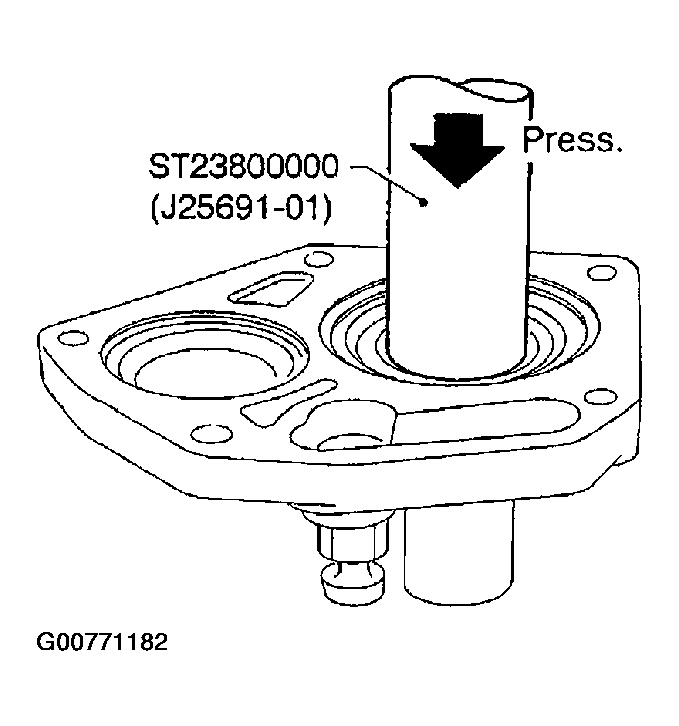
- Install front cover oil seal using Tool.
- Apply multi-purpose grease to seal lip.
- Tool number: ST23800000 (J25691-01)
 Courtesy of NISSAN MOTOR CO., U.S.A.
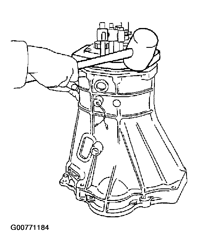
- Apply sealant to mating surface of transmission case as shown in Fig 2.
- Install adapter plate into transmission case by lightly tapping it using a soft hammer.
 Courtesy of NISSAN MOTOR CO., U.S.A.
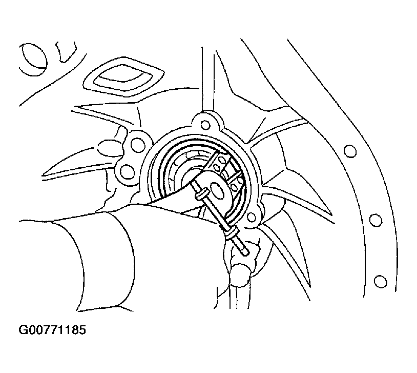
- Install main drive gear ball bearing snap ring.
 Courtesy of NISSAN MOTOR CO., U.S.A.
- Apply sealant to mating surface of adapter plate as shown in Fig 5.
 Courtesy of NISSAN MOTOR CO., U.S.A.
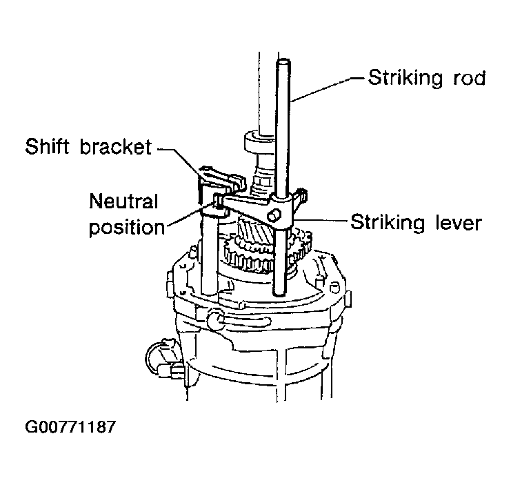
- Place shift forks in neutral position.
- Install striking lever and striking rod onto adapter plate and align striking lever with shift brackets.
 Courtesy of NISSAN MOTOR CO., U.S.A.
- Install rear extension.
- Tighten rear extension bolts equally in a crisscross pattern.
- Rear extension bolts: 16 - 19 N.m (1.6 - 2.0 kg-m, 12 - 14 ft-lb)
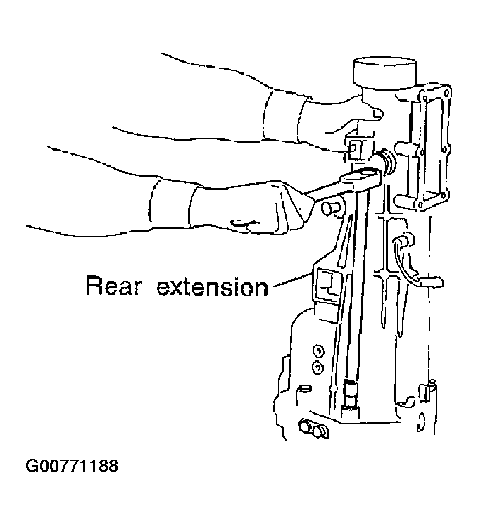 Courtesy of NISSAN MOTOR CO., U.S.A.
- Install striking lever retaining pin.
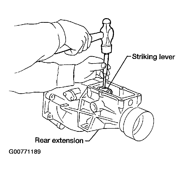 Courtesy of NISSAN MOTOR CO., U.S.A.
- Select counter gear front bearing shim. Refer to
COUNTERSHAFT FRONT BEARING SHIM .
- Allowable clearance (A) from bearing surface to transmission case: 0 - 0.16 mm (0 - 0.0063 in)
- Install new gasket and front cover.
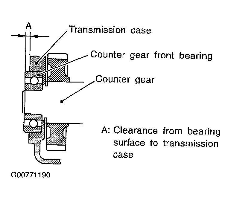 Courtesy of NISSAN MOTOR CO., U.S.A.
- Apply sealant to front cover bolts. Tighten front cover bolts.
- Install check ball, check spring, select check plungers and return springs.
- Apply sealant to select check plugs. Tighten select check plugs.
- Install control housing and new gasket.
- Control housing bolts: 14 - 18 N.m (1.4 - 1.8 kg-m, 10 - 13 ft-lb)
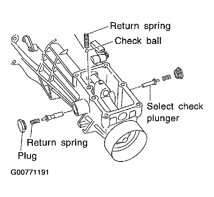 Courtesy of NISSAN MOTOR CO., U.S.A.