Hazard Reminder Check
- Check Hazard Warning Lights
Using hazard switch, ensure hazard warning lights flash. If hazard warning lights flash, go to next step. If hazard warning lights do not flash, check hazard warning light circuit. See appropriate wiring diagram in EXTERIOR LIGHTS article.
- Check Hazard Reminder Operation
Turn ignition off. Disconnect Smart Entrance Control Unit (SECU) harness connector. Using a jumper wire, connect terminal No. 7 (Orange/Black wire) at SECU harness connector to ground. See WIRING DIAGRAMS
. If hazard warning lights illuminate, hazard reminder is okay. If hazard warning lights do not illuminate, go to next step.
- Check Multi-Remote Control Relay
Disconnect multi-remote control relay. Measure resistance between multi-remote control relay terminal No. 2 and terminals No. 3, 5, 6 and 7. See Fig 1
. If resistance is 5 ohms or less for any measurement, replace multi-remote control relay. If all measurements are more than 5 ohms, go to next step.
- Connect a fused jumper wire between positive battery terminal and multi-remote control relay terminal No. 1. Using a test light, check for voltage at multi-remote control relay terminal No. 2. If voltage is present, go to next step. If voltage is not present, replace multi-remote control relay.
- Connect a fused jumper wire between positive battery terminal and multi-remote control relay terminal No. 1. Connect another jumper wire between negative battery terminal and multi-remote control relay terminal No. 2. Check continuity between multi-remote control relay terminals No. 3 and 5, and between terminals No. 6 and 7. If continuity is present, multi-remote control relay is okay. Go to next step. If continuity is not present, replace multi-remote control relay.
- Check Multi-Remote Control Relay Power Supply
Disconnect multi-remote control relay. Using DVOM, measure voltage between ground and terminal No. 1 (White/Green wire) at multi-remote control relay connector. See WIRING DIAGRAMS
. If battery voltage is present, go to next step. If battery voltage is not present, check fuse No. 5 (15-amp), located in fuse block. Check for open or short in wiring harness between multi-remote control relay and fuse. Repair as necessary.
- Check Multi-Remote Control Relay Circuit
Using DVOM, measure voltage between terminals No. 3 (White/Green wire) and No. 5 (Green/Black wire) at multi-remote control relay connector. Battery voltage should be present. Measure voltage between terminals No. 6 (White/Green wire) and No. 7 (Green/Yellow wire) at multi-remote control relay connector. Battery voltage should be present. If voltage is as specified, check for open or short in wiring harness between multi-remote control relay and SECU. If voltage is not as specified, check for open or short in wiring harness between multi-remote control relay and fuse, or between multi-remote control relay and turn signal lights. Repair as necessary.
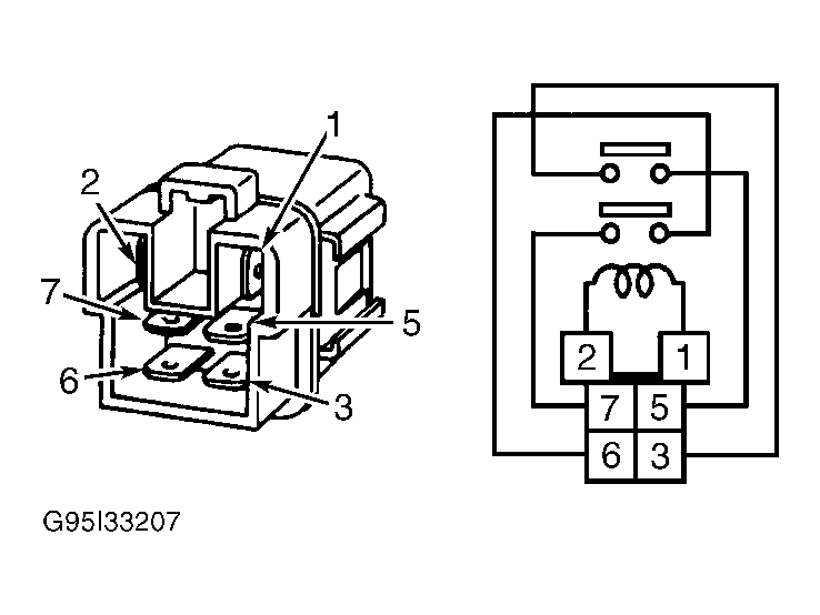 Courtesy of NISSAN MOTOR CO., U.S.A.