1979 Pickups
- With engine idling at normal operating temperature, disconnect anti-dieseling solenoid valve. Engine should stall. If not, replace solenoid assembly.
- Connect voltmeter to harness side of solenoid connector and to ground. Connect solenoid side of connector directly to positive battery terminal.
- On models with manual transmission, disconnect clutch pedal switch. Depress clutch pedal and shift transmission into 4th gear. On models with automatic transmission, place transmission shift lever in Neutral.
- On all models, increase engine speed to 2500-3000 RPM, then quickly close throttle valve. At this time, voltmeter needle should deflect from 12 to zero (0) volts. If not, either the fuel shut-off vacuum switch, Neutral switch (Man. Trans.), or inhibitor switch (Auto. Trans.) is defective.
- To determine defective part, reconnect clutch pedal switch (Man. Trans.). Disconnect fuel shut-off vacuum switch. Connect an ohmmeter to vacuum switch terminals. See Fig 1.
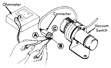 Courtesy of NISSAN NORTH AMERICA, INC.
- Increase engine speed to 2500-3000 RPM, then quickly close throttle valve. At this time, check continuity between terminals "A" and "B", and between terminals "A" and "C" of vacuum switch connector.
- Polarity should reverse between terminals "A" and "B" and between "A" and "C". If not, vacuum switch is defective and should be replaced.
- Reconnect vacuum switch connector. Repeat test steps 2) through 4). If voltmeter needle does not deflect from 12 to zero (0) volts, Neutral switch (Man. Trans.) or inhibitor switch (Auto. Trans.) is defective and should be replaced.
- To check inhibitor switch relay on automatic transmission models, remove relay from fender well, next to battery. Apply 12 volts across relay terminals No. 1 and 4. See Fig 2.
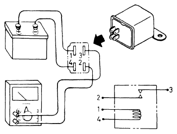 Courtesy of NISSAN NORTH AMERICA, INC.
- Make sure continuity exists between terminals No. 2 and 3. Check that continuity does not exist between terminals No. 2 and 3 when no voltage is applied. If test results are as specified, inhibitor switch relay is functioning properly. If not, replace relay.