Montero Sport
- If Scan Tool (MB991502) is not available, go to next step. If scan tool is available, turn ignition off. Connect scan tool to Data Link Connector (DLC). Turn ignition switch on. If tone alarm of scan tool sounds while turning ignition switch on, go to step 5. If alarm does not sound, go to step 3
- Turn ignition off. Using Data Link Connector (DLC) adapter (MB991529) connect DVOM to ground terminals No. 4 and 5 and ETACS-ECU terminal No. 9 of DLC. See Fig 1. Turn ignition switch on. If voltmeter needle deflects while turning ignition switch on, go to step 5. If needle does not deflect, go to next step.
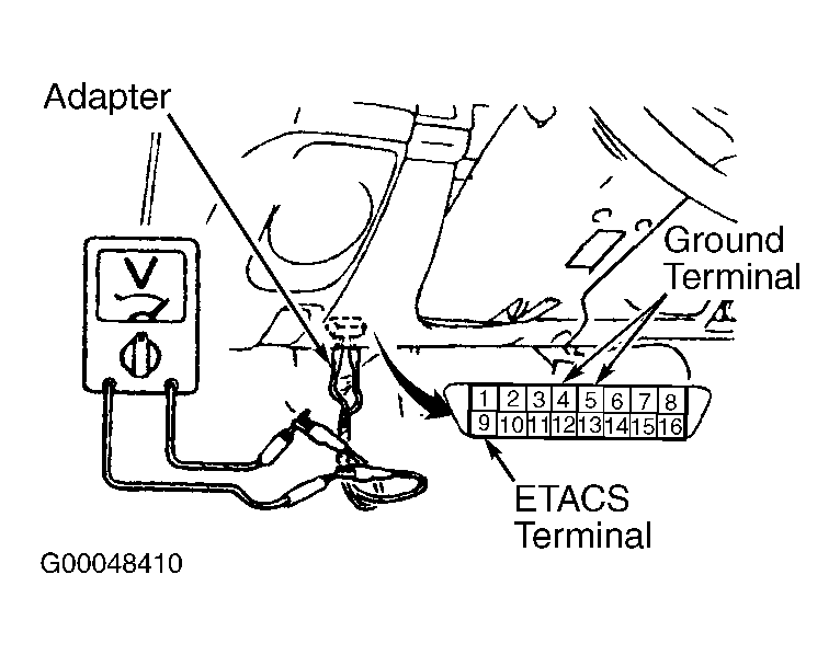 Courtesy of MITSUBISHI MOTOR SALES OF AMERICA.
- Disconnect ETACS-ECU 12-pin connector D-11. Turn ignition on. Using DVOM, measure voltage between ETACS-ECU connector terminal No. 3 (Black/White wire) and ground. If voltage is present, replace ETACS-ECU and retest system. If voltage is not present, check connector D-11 for damage or bent terminals. Repair if necessary. If connector is okay, go to next step.
- Check Black/White wire between ignition switch and ETACS-ECU. Repair wire and then retest system.
- Test power window relay. See POWER WINDOW RELAY TEST under COMPONENT TESTS. If relay is okay, go to next step. If relay is faulty, replace and then retest system.
- Disconnect power window relay connector C-75X. Measure voltage between power window relay terminal No. 4 (Blue/Red wire) and ground. If voltage is present, go to step 8. If voltage is not present, go to next step.
- Check Blue/Red wire between ETACS-ECU and power window relay. See WIRING DIAGRAMS . Repair wiring if damaged, then retest system. If wiring is okay, replace ETACS-ECU then retest system.
- Measure resistance between power window relay connector terminal No. 2 (Black wire) and ground. If resistance is less than 12 ohms, go to step 10. If resistance is more than 2 ohms, go to next step.
- Check connector C-75X for damaged or corroded terminals. Check black wire between connector C-75X and ground. See WIRING DIAGRAMS . Repair as necessary, then retest system.
- Measure voltage between power window relay connector terminal No. 3 (Red/Black wire) and ground. If battery voltage is present, go to step 12. If battery voltage is not present, go to next step.
- Inspect Red/Black wire between fusible link No. 4 and power window relay connector C-75X. Repair wiring as necessary then retest system.
- Disconnect power window main switch connector. Measure voltage between power window main switch terminal No. 13 (Blue wire) and ground. See Figure. If battery voltage is present go to step 14. If voltage is not present, go to next step.
- Check Blue wire between power window relay and power window main switch. Inspect connectors for damaged or corroded terminals. Repair as necessary, then retest system.
- Measure resistance between power window main switch terminal No. 12 (Black wire) and ground. If resistance is less than 2 ohms, replace power window main switch. Retest system. If resistance is more than 2 ohms, go to next step.
- Check Black wire and connectors between power window main switch and ground. Repair as necessary, then retest system.