Test No. 9
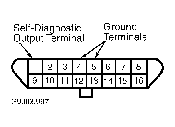
- Turn ignition off. Using an analog voltmeter, check for temporary voltage sweep between Data Link Connector (DLC) terminals No. 4 or 5 and No. 9. See Fig 1
. If voltmeter deflects once when ignition switch is operated, any door opens or closes or left front or right front door switch is actuated, problem is intermittent. Retest system. If voltmeter does not deflect once when ignition switch is operated, any door opens or closes or left front or right front door switch is actuated, go to step 8
. If voltmeter does not deflect once when ignition switch is operated, go to step 7
. If voltmeter does not deflect once when any door opens or closes or left front or right front door switch is actuated, go to next step.
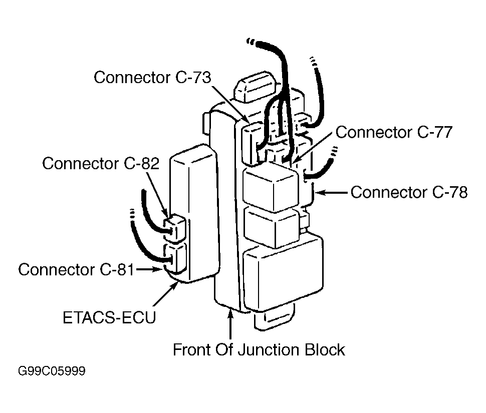
- Ensure ignition is off. Remove ETACS-ECU from junction block. Connect connector C-84. Connector C-84 is large connector above ETACS-ECU connector. Measure voltage between ground and ETACS-ECU connector C-86, terminal No. 2. See Fig 2
. If voltage is about 12 volts, go to next step. If voltage is not about 12 volts, repair Red/Black wire between fuse and ETACS-ECU.
- Remove left and right front door switch. Check continuity of each door switch. Continuity should exist between all terminals with switch released (ON) and no continuity with switch depressed (OFF). If door switch continuity is not as specified, replace switch and retest system. If left door switch is okay, go to next step. If right door switch is okay, go to step 5
.
- Connect connector C-87. Connector C-87 is located below ETACS-ECU connector. Check for continuity on Blue/Green wire between ETACS-ECU connector C-86, terminal No. 13 and left door switch connector. Repair Blue/Green wire as necessary and retest system. If Blue/Green wire is okay, go to step 6
.
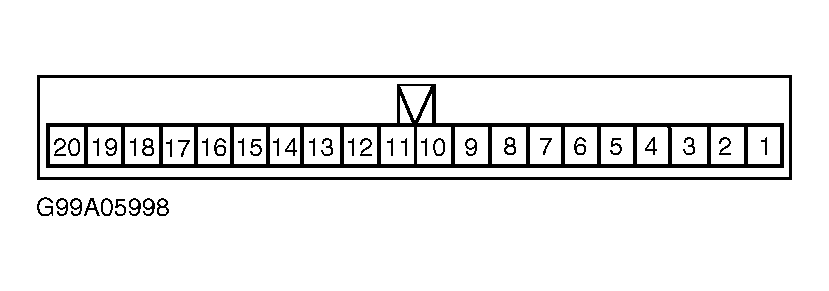
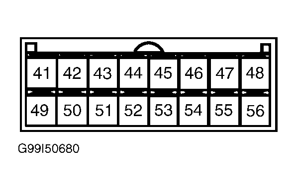
- Check for continuity on Blue/Green wire between ETACS-ECU connector C-82, terminal No. 56 and right door switch connector. See Fig 3
and Fig 4
. Repair Blue/Green wire as necessary and retest system. If Blue/Green wire is okay, go to next step.
- Check Black wire between ground and left and right door switch connector. Repair Black wire as necessary and retest system. If Black wire is okay, replace ETACS-ECU.
- Ensure ignition is off. Remove ETACS-ECU from junction block. Connect connector C-73. Connector C-73 is top left connector on junction block. See Fig 3
. Turn ignition on. Measure voltage between ground and ETACS-ECU connector C-86, terminal No. 11. If voltage is not about 12 volts, repair Black/White wire between ETACS-ECU connector C-86, terminal No. 11 and ignition switch. See WIRING DIAGRAMS
. Retest system. If voltage is about 12 volts, repair Black wire between ETACS-ECU connector C-86, terminal No. 1 and ground.
- Turn ignition off. Remove front ECU from engine compartment relay box. Measure voltage between ground and front ECU harness connector A-09X, terminal No. 16. See Figure
. Front ECU harness connector A-09X is part of engine compartment relay box. If voltage is about 12 volts, go to next step. If voltage is not about 12 volts, repair Red/Black wire between fuse No. 4 and front ECU harness connector A-09X terminal No. 16. See WIRING DIAGRAMS
.
- Ensure ignition is off. Connect scan tool to DLC. Check diagnostic trouble codes. If codes No. 11 or 13 are displayed, replace front ECU and retest system. If codes No. 12 or 21 are displayed, repair Orange/Black wire between front ECU harness connector A-09X, terminal No. 17 and ETACS-ECU connector C-82, terminal No. 42. See Figure
, Fig 3
and Fig 4
. See WIRING DIAGRAMS
.
 Courtesy of MITSUBISHI MOTOR SALES OF AMERICA.
 Courtesy of MITSUBISHI MOTOR SALES OF AMERICA.
 Courtesy of MITSUBISHI MOTOR SALES OF AMERICA.
 Courtesy of MITSUBISHI MOTOR SALES OF AMERICA.