Diagnostic Procedure
- Connect scan tool to Data Link Connector (OBD-II DLC) under instrument panel. Start engine and let idle. Using scan tool, check data list item No. 22 (crankshaft position sensor). Check idle speed. Turn on A/C and check idle up speed. On 2.4L, idle speed should be 650-850 RPM with A/C off and 750-950 RPM with A/C on. On 3.0L, idle speed should be 600-800 RPM with A/C off and 800-1000 RPM with A/C on. If idle speeds are as specified, problem is intermittent. See INTERMITTENT DIAGNOSTIC TROUBLE CODES
under CIRCUIT TESTS. If idle speed(s) are not as specified, go to next step.
- Disconnect IAC motor 6-pin connector. Turn ignition on. Check voltage between ground and IAC motor connector terminal No. 2. Also, check voltage between ground and IAC motor connector terminal No. 5. If battery voltage exists at each terminal, go to next step. If battery voltage does not exist at one or both terminals, repair wiring between appropriate IAC motor connector terminal and MFI relay, then go to step 9
.
- Turn ignition off. Check resistance between IAC motor connector terminal No. 2 and either terminal No. 1 or 3 (component side). Also, check resistance between IAC motor connector terminal No. 5 and either terminal No. 4 or 6 (component side). Each resistance should be 28-33 ohms at 68°F (20°C). If each resistance is as specified, go to next step. If any resistance is not as specified, replace IAC motor assembly, then go to step 9
.
- Remove IAC motor. Connect Test Harness (MB991709) to IAC motor. Check for IAC motor operation when battery positive terminal is jumpered to IAC motor connector terminal No. 2 (component side) and battery negative terminal is jumpered to IAC motor connector terminals No. 1 and 3 (component side). See Fig 1
. Check for IAC motor operation when battery positive terminal is jumpered to IAC motor connector terminal No. 5 (component side) and battery negative terminal is jumpered to IAC motor connector terminals No. 4 and 6 (component side). IAC motor should operate at voltage application to each listed terminal combination. If IAC motor performs as specified, reinstall IAC motor, then go to next step. If IAC motor does not perform as specified, replace IAC motor, then go to step 9
.
- Check IAC motor connector. If problem exists, repair as necessary and go to step 9
. If problem does not exist, go to next step.
- Disconnect ECM 26-pin connector C-35 or PCM 35-pin connector C-39. Turn ignition on. Check voltage between ground and ECM connector C-35 terminals 4, 5, 17 and 18, or PCM connector C-39 terminals No. 14, 15, 28 and 29. Battery voltage should exist at each terminal. If voltages are as specified, go to next step. If voltages are not as specified, repair appropriate wire between ECM/PCM and IAC motor, then go to step 9
.
- Turn ignition off. Check ECM connector C-35 or PCM connector C-39. If problem exists, repair connector, then go to step 9
. If problem does not exist, go to next step.
- Disconnect IAC motor 6-pin connector. Install Test Harness (MB991709) between connector halves. Connect lab scope pick-up, in turn, to IAC motor connector terminals No. 1, 3, 4 and 6. If checking at ECM/PCM, connect lab scope pick-up, in turn, to ECM connector C-35 terminals No. 4, 5, 17 and 18, or PCM connector C-39 terminals No. 14, 15, 28 and 29. Start engine and let idle. Turn A/C switch on. Check waveform when IAC motor increases idling speed (display lasts less than one second). Waveform should show normal pattern. See Fig 2
. If waveform is normal, problem is intermittent. See INTERMITTENT DIAGNOSTIC TROUBLE CODES
under CIRCUIT TESTS. If waveform is not normal, replace ECM/PCM, then go to next step.
- Using scan tool, clear DTCs. Test drive vehicle following OBD-II drive cycle other monitor pattern. See
OBD-II DRIVE CYCLES under VERIFYING REPAIRS in SELF-DIAGNOSTICS - INTRODUCTION article. Check for DTCs. Confirm DTC does not reset. See
VERIFYING REPAIRS in SELF-DIAGNOSTICS - INTRODUCTION article.
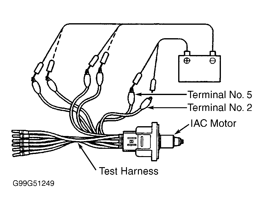 Courtesy of MITSUBISHI MOTOR SALES OF AMERICA.
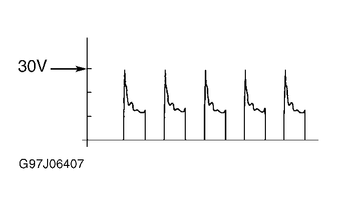 Courtesy of MITSUBISHI MOTOR SALES OF AMERICA.