Diagnostic Procedure
- Connect an external tachometer. Using scan tool, read data list item No. 22 (crankshaft position sensor). Check engine RPM during cranking and at idle. If RPM displayed on scan tool and tachometer are equal, go to next step. If RPM displayed on scan tool and tachometer are not equal, go to step 4
.
- Using oscilloscope, perform crankshaft position sensor waveform check. Connect Test Harness (MD998478) between Crankshaft Position (CKP) sensor and harness connector. Connect analyzer special patterns pick-up to CKP sensor terminal No. 2. If test harness is not available, connect analyzer special patterns pick-up to PCM connector B-109 terminal No. 45. Go to next step.
- With engine idle speed stable, compare CKP sensor waveform to known-good waveform. See Fig 1
. If waveform is okay, go to step 5
. If waveform is not okay, go to next step.
- Check CKP sensor connector, PCM 26-pin connector B-109, and wiring between PCM and CKP sensor connector. Check CKP sensor and sensing plate for proper installation. If problem exists, repair as necessary. If problem does not exist, replace CKP sensor.
- Turn ignition off. Disconnect fuel injector connector. Check resistance between fuel injector terminals. Resistance should be 13-16 ohms at 68°F (20°C). If resistance is as specified, go to next step. If resistance is not as specified, replace fuel injector.
- Connect fuel injector connector. Using stethoscope, check fuel injector operating sound during cranking or at idle. Ensure frequency of operating sound increases as engine RPM increases. If operating sound is heard from fuel injector, go to next step. If no operating sound is heard from a fuel injector, check fuel injector connectors and fuel injector drive circuit. See DTC P0201-P0206: INJECTOR NO. 1-6 CIRCUIT MALFUNCTION
.
- Start and warm engine to normal operating temperature. Turn all accessories off. Increase engine speed to 2500 RPM. Using scan tool, read data list item No. 81 (long-term fuel compensation). If fuel trim is -12.5-12.5 percent (during closed loop), go to next step. If fuel trim is not -12.5-12.5 percent (during closed loop), check fuel trim fault. See DTC P0170 & P0173: FUEL TRIM MALFUNCTION
.
- Using scan tool, read data list item No. 82 (short-term fuel compensation) with engine speed at 2500 RPM. If fuel trim is -20.0-20.0, go to next step. If fuel trim is not -20.0-20.0, check fuel trim fault. See DTC P0170 & P0173: FUEL TRIM MALFUNCTION
.
- Using scan tool, read data list item No. 21 (engine coolant temperature). If temperature displayed on scan tool is equal to actual engine coolant temperature, go to next step. If temperature displayed on scan tool is not equal to actual engine coolant temperature, check ECT circuit. See DTC P0115: ENGINE COOLANT TEMPERATURE (ECT) CIRCUIT MALFUNCTION
.
- Check ignition coil, spark plugs and spark plug wires. Check compression pressure. See
BASIC DIAGNOSTIC PROCEDURES article. Repair as necessary.
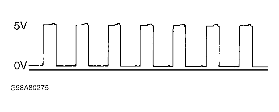 Courtesy of MITSUBISHI MOTOR SALES OF AMERICA