MPI Control Relay
- This step checks ignition supply voltage to ECM. Disconnect ECM harness connector. Turn ignition on. Using DVOM, measure voltage between ECM harness connector terminal No. 62 and vehicle ground. See Figure
. If voltage measured is battery voltage, go to step 2. If voltage is not battery voltage, check and repair circuit between ignition switch and ECM harness connector.
- This step checks battery supply voltage of control relay. Using DVOM, measure voltage between terminal No. 10 of relay harness connector and vehicle ground. See Fig 1
. If voltage measured is battery voltage, go to step 3. If voltage is not battery voltage, check and repair circuit between battery and control relay.
- This step checks continuity of circuit between control relay and ECM. Disconnect ECM connector. Using DVOM, check continuity between control relay harness connector terminal No. 8 and ECM harness connector terminal No. 108. If continuity exists, go to step 4. If continuity does not exist, check and repair circuits between control relay harness connector and ECM.
- This step checks continuity of circuit between control relay and ECM. Check continuity between control relay harness connector terminal No. 4 and ECM harness connector terminals No. 12 and 25. If continuity exists, go to step 5. If continuity does not exist, check and repair circuits between control relay harness connector and ECM.
- This step checks supply voltage to control relay actuator. Connect ECM and MPI control relay connectors. Using DVOM, backprobe control relay terminal No. 5. With engine cranking, voltage should be 8 volts or greater. Start engine and run at 2500 RPM or greater. If voltage is battery voltage, harness is okay. If voltage is not battery voltage, go to step 6.
- If control relay tests okay in steps 6 through 8, replace ECM. Connect 12-volt power source between relay terminals No. 8 and 10. Connect positive lead to terminal No. 10. With relay energized, battery voltage should exist between terminals No. 4 and 8 and between terminals No. 5 and 8. With power source removed, voltage should not exist.
- Move 12-volt power source to relay terminals No. 6 and 9. Connect positive lead to terminal No. 9. With relay energized, continuity should exist between terminals No. 2 and 3. With power source removed, continuity should not exist.
- Move 12-volt power source to relay terminals No. 3 and 7. Connect positive lead to terminal No. 3. With relay energized, battery voltage should exist between terminals No. 2 and 7. With power source removed, voltage should not exist. Replace control relay if any measurements are not as specified.
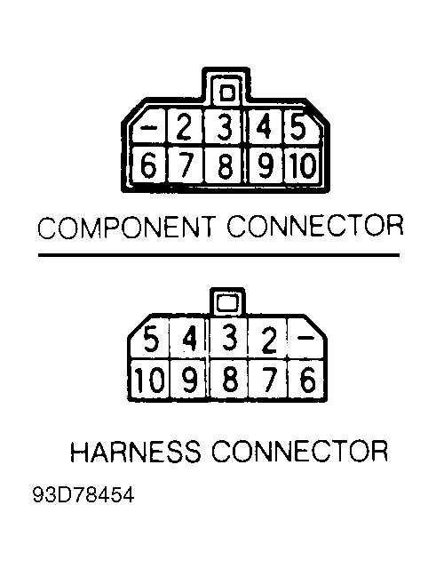 Courtesy of MITSUBISHI MOTOR SALES OF AMERICA.