Transmission Disassembly
- Ensure transmission case is clean of dirt and grease prior to disassembly. Remove wire harness clamp and throttle cable from converter housing. Remove control shaft lever. Remove OD solenoid valve and neutral safety switch. Remove transfer case. See appropriate article in the TRANSFER CASES section. Remove torque converter.
- Remove oil pump bolts. Using appropriate puller, remove oil pump assembly from transmission case. Remove converter housing bolts. Note length and location of bolts. While holding input shaft, remove converter housing. Remove extension housing and gasket. Note bolt length and location. Remove oil supply tube (if equipped). Remove transfer adapter (if equipped).
- Remove snap ring, speedometer drive gear, lock ball and remaining snap ring from output shaft. Remove staked area on lock plate. Remove governor lock plate bolt. Using a screwdriver, lift retaining clip from hole in output shaft. Remove governor from output shaft. Remove oil pan bolts, oil pan and gasket. Inspect pan for metal or brass particles. Remove oil tubes by prying both ends of tube with screwdrivers. Remove oil strainer and gasket.
- Remove control valve assembly. See CONTROL VALVE ASSEMBLY
under ON-VEHICLE SERVICE. Raise control valve assembly slowly and remove throttle cable from throttle cam. Push throttle cable adapter with nut driver to disconnect throttle cable from case.
- Remove parking lock pawl. See PARKING LOCK PAWL
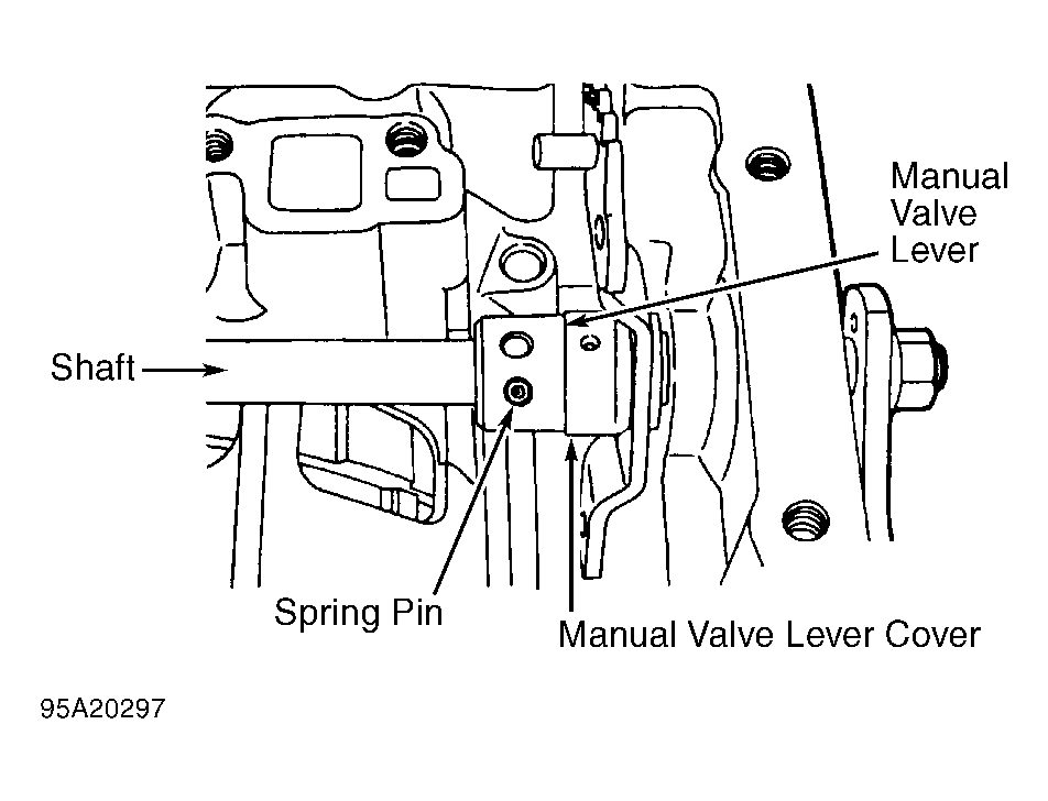
under ON-VEHICLE SERVICE. Using a screwdriver, move manual valve lever cover outward. Drive out spring pin, and then remove shaft and manual valve lever. See Fig 1
. Remove oil seal from manual valve shaft (if necessary).
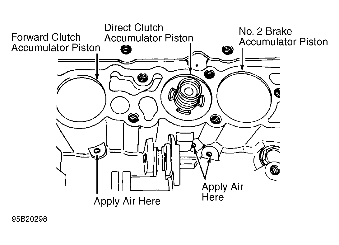
- Place shop cloth over accumulator pistons. Using compressed air, remove accumulator pistons and springs from transmission case. See Fig 2
. Note location of springs and pistons for reassembly reference.
- Remove input shaft, OD planetary gear and OD clutch as an assembly from transmission case. Remove OD case, forward clutch and direct clutch. Remove 2 center support bolts. See Figure
. Remove center support and sun gear as an assembly.
- Remove snap ring securing planetary assembly in transmission case. Remove intermediate shaft, clutch plates and planetary assembly from transmission case. Remove output shaft from transmission case. Remove No. 3 brake apply tube. Remove output shaft thrust bearing race No. 19 and thrust bearing No. 18 from transmission case.
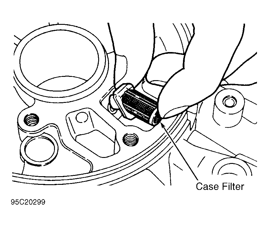
- Using calipers, measure pack clearance of No. 3 brake between disc and transmission case. Pack clearance should be .024-.1049" (.61-2.640 mm). If clearance is not as specified, inspect brake discs. Remove 3 phillips-head rear cover screws, rear cover and gasket. Remove case filter. See Fig 3
.
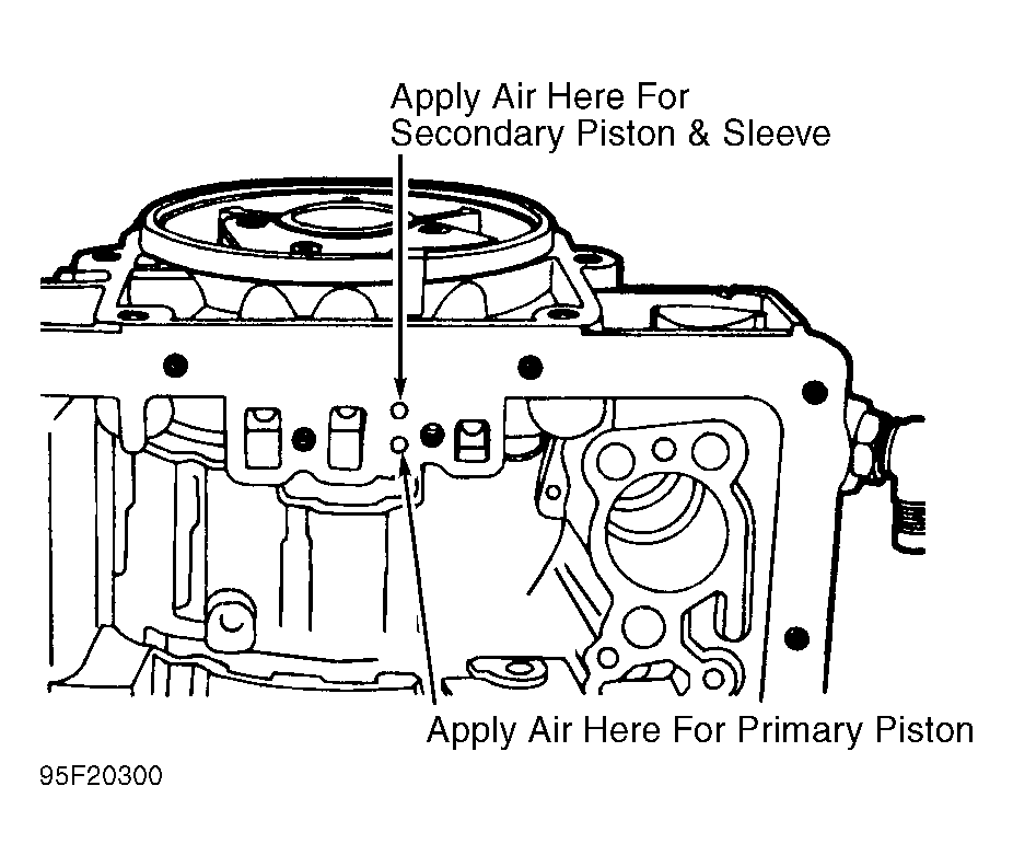
- Remove No. 3 brake pack and pressure plate. Using appropriate spring compressor, compress No. 3 brake return spring assembly. Remove snap ring. Remove spring assembly. Apply compressed air to appropriate transmission case oil hole, and remove No. 3 brake pistons and sleeve. See Fig 4
. Measure inside diameter of transmission case rear bushing. Replace transmission case if bushing diameter exceeds 1.504" (38.19 mm).
 Courtesy of MITSUBISHI MOTOR SALES OF AMERICA.
 Courtesy of MITSUBISHI MOTOR SALES OF AMERICA.
 Courtesy of MITSUBISHI MOTOR SALES OF AMERICA.
 Courtesy of MITSUBISHI MOTOR SALES OF AMERICA.