Disassembly and Assembly
- Place the transaxle clutch housing on a bench.
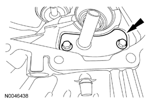
- Remove the 2 vent cover bolts and the vent cover.
 Courtesy of FORD MOTOR CO.
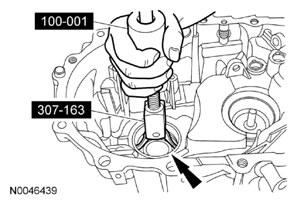
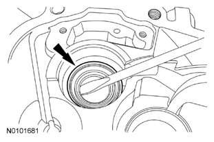
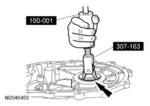
- Using the Slide Hammer and Stator Case Bearing Remover, remove the differential bearing cup.
- Inspect the cup for wear or damage. Install a new cup as necessary.
- Always install new bearings and cups as a set.
 Courtesy of FORD MOTOR CO.
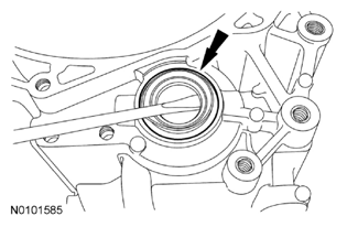
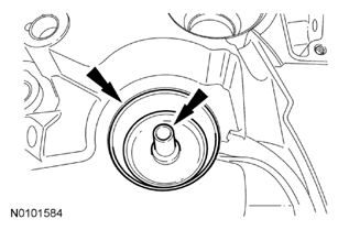
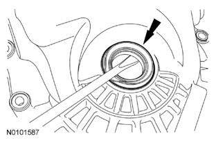
- Using a screwdriver, remove and discard the differential seal.
 Courtesy of FORD MOTOR CO.
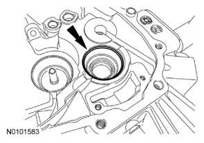
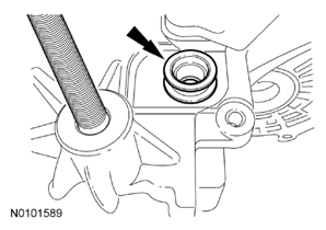
- Remove the input shaft bearing cup.
- Inspect the cup for wear or damage. Install a new cup as necessary.
- Always install new bearings and cups as a set.
 Courtesy of FORD MOTOR CO.
- Using a screwdriver, remove and discard the input shaft oil seal.
 Courtesy of FORD MOTOR CO.
- Remove the output shaft bearing cup and the funnel.
- Inspect the cup for wear or damage. Install a new cup as necessary.
- Always install new bearings and cups as a set.
 Courtesy of FORD MOTOR CO.
- Remove the shift control selector plate bolts and the shift control selector plate.
 Courtesy of FORD MOTOR CO.
- Working on the transaxle case:
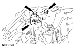
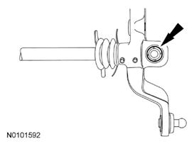
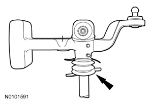
- Remove the 2 shift lever assembly bolts and separate the boot from the case.
- Separate the shift arm, boot and bushing from the shift lever assembly.
 Courtesy of FORD MOTOR CO.
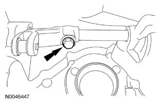
- Remove the control arm bolt.
 Courtesy of FORD MOTOR CO.
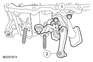
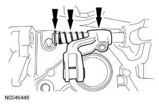
- Pull the shift lever outward, then remove the washer, spring and the control arm.
 Courtesy of FORD MOTOR CO.
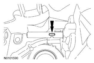
- Remove the control arm key.
 Courtesy of FORD MOTOR CO.
- Remove the shift lever from the case.
- Inspect all components for wear or damage. Install new components as necessary.
- Inspect the shift lever bushing and replace if necessary.
 Courtesy of FORD MOTOR CO.
- Remove the shift lever boot.
 Courtesy of FORD MOTOR CO.
- Remove the shift lever seal.
 Courtesy of FORD MOTOR CO.
- Remove the input shaft bearing cup and shims.
- Inspect the cup for wear or damage. Install a new cup as necessary.
- Always install new bearings and cups as a set.
- Remove the output shaft bearing cup and shims.
- Inspect the cup for wear or damage. Install a new cup as necessary.
- Always install new bearings and cups as a set.
- Using the Slide Hammer and Stator Case Bearing Remover, remove the differential bearing cup and shims.
- Inspect the cup for wear or damage. Install a new cup as necessary.
- Always install new bearings and cups as a set.
 Courtesy of FORD MOTOR CO.
- Remove and discard the differential oil seal.
 Courtesy of FORD MOTOR CO.