Pinpoint Test B: Transmission Control (TC) Switch Does Not Operate Correctly
- B1 TEST THE INSTRUMENT CLUSTER
- Connect the diagnostic tool.
- Using the scan tool, monitor the TC switch PID while cycling the TC switch.
- Does the TC switch PID cycle from closed to open?
- YES
: REFER to INSTRUMENT CLUSTER (IC), MESSAGE CENTER, AND WARNING CHIMES
article.
- NO
: Go to B2.
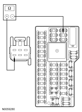
- B2 CHECK SJB FUSE 30 (5A)
- Key in OFF position.
- Check fuse: Smart Junction Box (SJB) Fuse 30 (5A)
- Is the resistance less than 5 ohms?
- YES
: Go to B3.
- NO
: Go to B4.
- B3 TEST THE TC SWITCH POWER CIRCUIT FOR AN OPEN
- Disconnect: Selector Lever Harness C3245
- Disconnect: SJB Fuse 30 (5A)
- Measure the resistance between selector lever harness C3245-6, circuit CBP30 (YE/BU) and the output side of SJB fuse 30 (5A).
 Courtesy of FORD MOTOR CO.
- Is the resistance less than 5 ohms?
- YES
: Go to B5.
- NO
: REPAIR circuit CBP30 (YE/BU). RECONNECT all components. TEST the system for normal operation.
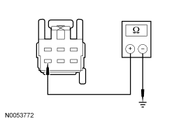
- B4 TEST THE TC SWITCH POWER CIRCUIT FOR A SHORT TO GROUND
- Disconnect: Selector Lever Harness C3245
- Disconnect: SJB Fuse 30 (5A)
- Measure the resistance between selector lever harness C3245-6 circuit CBP30 (YE/BU) and ground.
 Courtesy of FORD MOTOR CO.
- Is the resistance greater than 10,000 ohms?
- YES
: Go to B6.
- NO
: REPAIR circuit CBP30 (YE/BU) for a short to ground. RECONNECT all components. TEST the system for normal operation.
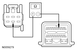
- B5 TEST THE TC SWITCH SIGNAL CIRCUIT FOR AN OPEN
- Disconnect: PCM C175b
- Measure the resistance between selector lever harness C3245-5, circuit CET34 (BN/GN) and PCM C175b-16, circuit CET34 (BN/GN).
 Courtesy of FORD MOTOR CO.
- Is the resistance less than 5 ohms?
- YES
: Go to B7.
- NO
: REPAIR circuit CET34 (BN/GN) for an open. RECONNECT all components. TEST the system for normal operation.
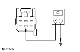
- B6 TEST THE TC SWITCH SIGNAL CIRCUIT FOR A SHORT TO GROUND
- Measure the resistance between selector lever harness C3245-5, circuit CET34 (BN/GN) and ground.
 Courtesy of FORD MOTOR CO.
- Is the resistance greater than 10,000 ohms?
- YES
: Go to B7.
- NO
: REPAIR circuit CET34 (BN/GN) for a short to ground. TEST the system for normal operation.
- B7 TEST THE TC SWITCH
- Measure the resistance between selector lever connector C3245-5 and C3245-6, component side, while cycling the TC switch.
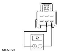 Courtesy of FORD MOTOR CO.
- Is the resistance less than 5 ohms when pressed and greater than 10,000 ohms when released?
- YES
: INSTALL a new PCM. REFER to ELECTRONIC ENGINE CONTROLS
article. TEST the system for normal operation.
- NO
: INSPECT the selector lever wiring harness for damage and repair as necessary. If the selector lever wiring harness is not damaged, INSTALL a new selector lever knob. TEST the system for normal operation.