Pinpoint Test A: The Shift Interlock System Does Not Release/Lock Correctly
- A1 TEST THE BRAKE LIGHTS
- Apply the brake pedal and view the brake lights.
 Courtesy of FORD MOTOR CO.
- Do the brake lights illuminate?
- Yes
: GO to A7.
- No
: GO to A2.
- A2 TEST FUSE 14 (15A)
- Check fuse: Fuse 14 (15A).
- Is the resistance of the fuse 5 ohms or less?
- Yes
: GO to A4.
- No
: GO to A3.
- A3 TEST CIRCUIT 10 (LG/RD) FOR A SHORT TO GROUND
- Key in OFF position.
- Disconnect: Brake Pedal Position (BPP) Switch C278.
- Measure the resistance between C278 pin 1, circuit 10 (LG/RD), harness side and ground.
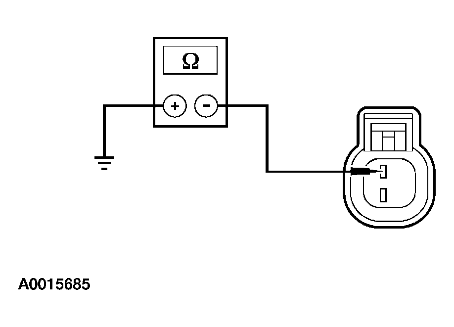 Courtesy of FORD MOTOR CO.
- Are the resistances less than 10,000 ohms?
- Yes
: REPAIR circuit 10 (LG/RD). TEST the system for normal operation.
- No
: GO to A4.
- A4 TEST CIRCUIT 10 (LG/RD) FOR AN OPEN
- Measure the resistance between Fuse 14 (15A), output side and C278 pin 1, circuit 10 (LG/RD), harness side.
 Courtesy of FORD MOTOR CO.
- Is the resistance less than 5 ohms?
- Yes
: GO to A5.
- No
: REPAIR circuit 10 (LG/RD). TEST the system for normal operation.
- A5 TEST THE BRAKE PEDAL POSITION (BPP) SWITCH
- Measure the resistance between BPP switch pin 1 and pin 2, while open (off) and closed (on).
 Courtesy of FORD MOTOR CO.
- Is the resistance of the switch greater than 10,000 ohms while OFF and 5 ohms or less while ON?
- Yes
: GO to A6.
- No
: INSTALL a new BPP switch. TEST the system for normal operation.
- A6 TEST CIRCUIT 810 (RD/LG) FOR A SHORT TO GROUND
- Disconnect: Shift Lock Actuator C2008.
- Measure the resistance between C2008 pin 1, circuit 810 (RD/LG), harness side and ground.
 Courtesy of FORD MOTOR CO.
- Are the resistances less than 10,000 ohms?
- Yes
: REPAIR circuit 810 (RD/LG). TEST the system for normal operation.
- No
: GO to A7.
- A7 TEST CIRCUIT 810 (RD/LG) FOR AN OPEN
- Measure the resistance between C2008 pin 1, circuit 810 (RD/LG) harness side and C278 pin 1, circuit 810 (RD/LG) harness side.
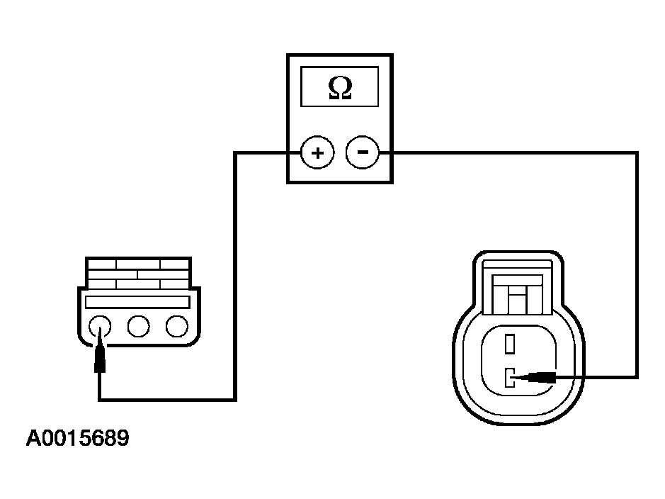 Courtesy of FORD MOTOR CO.
- Is the resistance less than 5 ohms?
- Yes
: GO to A8.
- No
: REPAIR circuit 810. TEST the system for normal operation.
- A8 TEST FOR B+ ON CIRCUIT 1087C (OG)
- Key in ON position.
- Measure the voltage between C2008 pin 3, circuit 1087C (OG) harness side and ground.
 Courtesy of FORD MOTOR CO.
- Is there battery voltage?
- Yes
: GO to A12.
- No
: GO to A9.
- A9 TEST FUSE 57 (10A)
- Key in OFF position.
- Check fuse: Fuse 57 (10A).
- Is the resistance less than 5 ohms?
- Yes
: GO to A11.
- No
: GO to A10.
- A10 TEST CIRCUIT 1087C (OG) FOR A SHORT TO GROUND
- Measure the resistance between C2008 pin 3, circuit 1087C (OG) harness side and ground.
 Courtesy of FORD MOTOR CO.
- Are the resistances less than 10,000 ohms?
- Yes
: REPAIR circuit 1087C (OG). TEST the system for normal operation.
- No
: GO to A11.
- A11 TEST CIRCUIT 1087C (OG) FOR AN OPEN
- Measure the resistance between Fuse 57 (10A), output side and C2008 pin 3, circuit 1087C (OG) harness side.
 Courtesy of FORD MOTOR CO.
- Is the resistance less than 5 ohms?
- Yes
: GO to A12.
- No
: REPAIR circuit 1087C (OG) for an open. TEST the system for normal operation.
- A12 TEST CIRCUIT 57E (BK) FOR AN OPEN
- Measure the resistance between C2008 pin 2, circuit 57E (BK) harness side and ground.
 Courtesy of FORD MOTOR CO.
- Is the resistance less than 5 ohms?
- Yes
: INSTALL a new shift lock actuator. TEST the system for normal operation.
- No
: REPAIR circuit 57E (BK). TEST the system for normal operation.