Test Ab: Message Center/Trip Computer Switch Not Operating Correctly
- Connect New Generation Star (NGS) tester or equivalent scan tool to Data Link Connector (DLC). Turn ignition switch to RUN position. Using NGS tester, monitor Hybrid Electronic Cluster (HEC) module PID RESETSW and SELECT. Monitor both PID's while individually pressing each switch for 2 seconds. Monitor message center while pressing UNITS button of trip computer switch. If SELECT button was not acknowledged, go to step 2. If RESET button was not acknowledged, go to step 3. If UNITS button was not acknowledged, go to step 4. If all switches are acknowledged, go to step 5.
- Turn ignition switch to LOCK position. Disconnect trip computer switch harness connector C442. Measure resistance between terminals No. 2 and 6 at trip computer switch (component side). See Fig 1. Resistance should be 5 ohms or less when SELECT button is pressed and greater than 10 k/ohms when SELECT button in not pressed. If resistance is not as specified, replace trip computer switch. If resistance is as specified, repair White/Green wire between trip computer switch and HEC module.
- Turn ignition switch to LOCK position. Disconnect trip computer switch harness connector C442. Measure resistance between terminals No. 1 and 6 at trip computer switch (component side). See Fig 1. Resistance should be 5 ohms or less when RESET button is pressed and greater than 10 k/ohms when RESET button in not pressed. If resistance is not as specified, replace trip computer switch. If resistance is as specified, repair White/Blue wire between trip computer switch and HEC module.
- Turn ignition switch to LOCK position. Disconnect trip computer switch harness connector C442. Measure resistance between terminals No. 3 and 6 at trip computer switch (component side). See Fig 1. Resistance should be 5 ohms or less when UNITS button is pressed and greater than 10 k/ohms when UNITS button in not pressed. If resistance is not as specified, replace trip computer switch. If resistance is as specified, repair White/Violet wire between trip computer switch and HEC module.
- Turn ignition switch to LOCK position. Disconnect trip computer switch harness connector C442. Measure resistance between ground and terminal No. 6 (Black or Black/Orange wire) at trip computer switch harness connector C442. If resistance is 5 ohms or less, replace trip computer switch. If resistance is greater than 5 ohms, repair open in Black or Black/Orange wire.
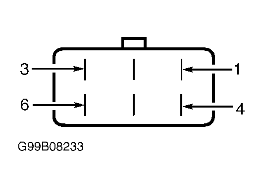 Courtesy of FORD MOTOR CO.