Starter Does Not Crank & Relay Does Not Click
- Verify battery condition. Battery voltage should be 12 volts or more. Load test battery at approximately one-half cold cranking amperage rating. See load tester manufacturer's instructions. If battery voltage is less than 12 volts or loaded battery voltage is less than 9.6 volts, service battery or charging system as necessary.
- Remove starter relay from power distribution box in engine compartment. Measure voltage between starter relay harness connector terminal No. 86 and ground with ignition switch in START position. If battery voltage is present, go to next step. If battery voltage is not present, go to step 4.
- Measure resistance between starter relay harness connector terminal No. 85 and ground with ignition switch in START position. If resistance is less than 5 ohms, install new starter relay and check system operation. If resistance is 5 ohms or greater, go to step 6 (manual transmission) or step 9 (automatic transmission).
- Remove starter diode from power distribution box. See Fig 1. Measure voltage between both diode connector terminals and ground with ignition switch in START position. If battery voltage is present at either terminal, install new diode and check system operation. If battery voltage is not present, go to next step.
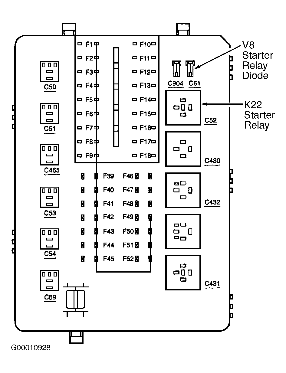 Courtesy of FORD MOTOR CO.
- Disconnect ignition switch. Measure resistance between ignition switch connector C456 terminal No. 5 (Gray/White wire) and both diode connector terminals in power distribution box. See WIRING DIAGRAMS . If resistance is 5 ohms or less on one terminal, replace ignition switch. See appropriate
STEERING COLUMN SWITCHES article in ACCESSORIES & EQUIPMENT. If resistance is greater than 5 ohms on both terminals, repair open Gray/White wire between ignition switch and power distribution box.
- Install starter relay. Disconnect start inhibit switch, located on clutch pedal bracket. Measure voltage between start inhibit switch harness connector Black/Yellow wire and ground with ignition switch in START position. If battery voltage is present, go to next step. If battery voltage is not present, repair Black/Yellow wire and check system operation.
- Measure resistance between start inhibit switch terminals. Resistance should be less than 5 ohms with clutch pedal depressed, and greater than 100,000 ohms with clutch pedal released. If resistance is as specified, go to next step. If resistance is not as specified, adjust start inhibit switch and retest. If resistance is still not as specified, replace start inhibit switch.
- Disconnect PCM harness connector C421, located underneath center console. Measure resistance between PCM harness connector terminal 82 and start inhibit switch terminal No. 1 (Black/Yellow wire). See Fig 2. If resistance is less than 5 ohms, reconnect start inhibit switch and go to step 12. If resistance is 5 ohms or greater, repair Black/Yellow wire between PCM connector and start inhibit switch connector.
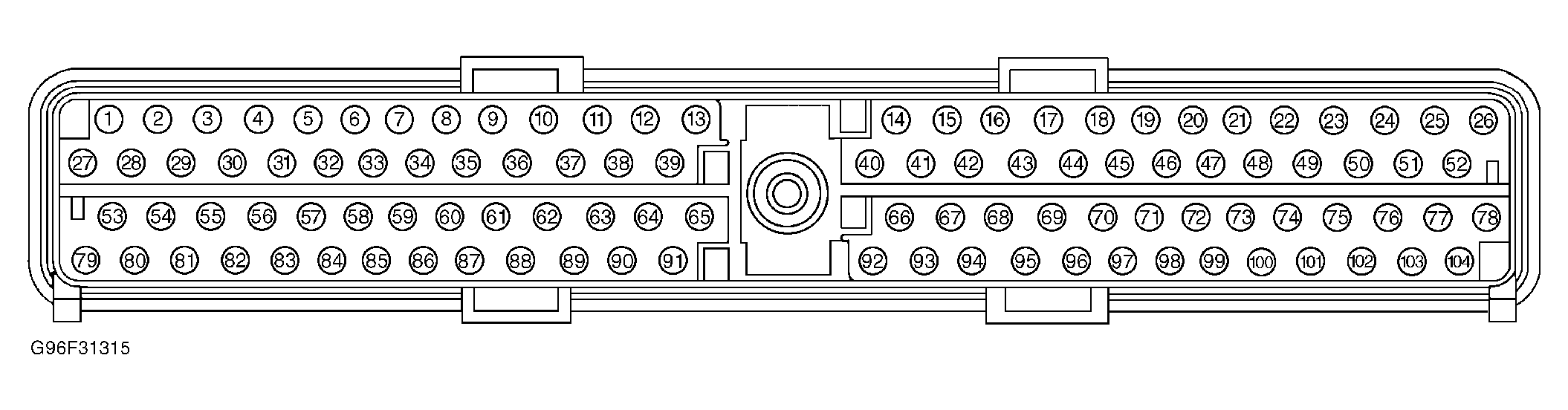 Courtesy of FORD MOTOR CO.
- Install starter relay. Disconnect Transmission Range (TR) sensor. Measure voltage between TR sensor connector terminal No. 3 (Black/Yellow wire) and ground with ignition switch in START position. If battery voltage is present, go to next step. If battery voltage is not present, repair Black/Yellow wire and check system operation.
- Disconnect PCM 104-pin connector C421. Measure resistance of Black/Green wire between PCM connector terminal No. 82 and TR sensor connector terminal No. 6. See Fig 2. If resistance is less than 5 ohms, go to next step. If resistance is 5 ohms or greater, repair Black/Green wire and check system operation.
- Measure resistance between TR sensor terminal No. 3 (Black/Yellow wire) and terminal No. 6 (Black/Green wire). If resistance is 5 ohms or less, reconnect TR sensor harness connector and go to next step. If resistance is greater than 5 ohms, adjust TR sensor using Sensor Alignment Tool (T94P-70010-AH). Recheck resistance. If resistance is still not as specified, replace TR sensor.
- Install EEC-V PCM breakout box. Connect a jumper wire between breakout box pins No. 82 and No. 77. Momentarily turn ignition switch to START position. If starter motor does not activate, go to STARTER DOES NOT CRANK & RELAY CLICKS . If starter motor activates, and vehicle is equipped with anti-theft system, go to appropriate
ANTI-THEFT SYSTEMS article. If starter motor activates, and vehicle is not equipped with anti-theft system, replace PCM and check system operation.