Power Door Lock Switch
- Disconnect negative battery cable. Unplug door lock switch connector. See DOOR LOCK ACTUATOR under REMOVAL & INSTALLATION. Measure resistance between switch terminals No. 1 (Blue/Red wire on mating connector) and No. 3 (Green/Orange wire on mating connector). See Fig 1. With switch in lock position, resistance should be greater than 10 k/ohms. With switch in unlock position, resistance should be less than 5 ohms.
- Measure resistance between switch terminals No. 1 (Blue/Red wire on mating connector) and No. 2 (Green/Red wire on mating connector). With switch in unlock position, resistance should be greater than 10 k/ohms. With switch in lock position, resistance should be less than 5 ohms. Replace switch if resistance is not as specified.
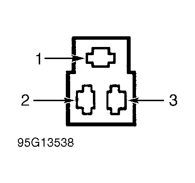 Courtesy of FORD MOTOR CO.