Rear Terminal Alternators: Disassembly
- Mark end housings and stator frame with scribe for reassembly reference. Remove through bolts. Separate front housing and rotor assembly from stator and rear housing. Remove brush springs from rear housing brush holder. Remove all nuts, washers and insulators from terminals on back of rear housing. Note color and location of insulators for later reassembly.
- Remove stator and rectifier assembly from rear housing. Remove brush holder, brushes, brush terminal insulator and press bearing from rear housing.
- Clamp front housing in vise using protective jaws. Remove drive pulley nut from rotor shaft using suitable tool (T65P-10300-B). Remove lock washer, drive pulley, fan and fan spacer from rotor shaft. Remove rotor from front housing and release housing from vise.
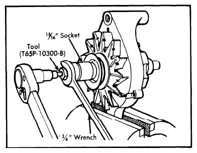 Courtesy of FORD MOTOR CO.
- Remove front bearing spacer from rotor shaft. Do not remove stop ring from rotor shaft unless it is damaged. Remove bearing retainer and bearing from front housing. Press bearing out if necessary. Remove radio suppression capacitor and battery terminal insulator from rectifier assembly.
- Using a 100 watt soldering iron, unsolder stator leads from rectifier assembly. Do not permit rectifiers to overheat. On 65 amp. alternators, use care not to cut stator load wires. Unsolder stator lead terminals from molded circuit board terminals. Use needle nose pliers to pull stator lead terminals upwards from rectifier assembly. Shake molten solder from terminals while hot.
- Disconnect stator neutral lead from flat type rectifiers by removing stator terminal screw, pressing it straight out of rectifier. Do not turn terminal screw during removal, as this will destroy retaining serrations. On stacked type rectifiers (with exposed diodes as contrasted with built-in diodes of flat type rectifiers), remove stator terminal screw by turning it 1/4" turn to unlock it. Ground screw can be removed in similar manner, depending on type of rectifier.
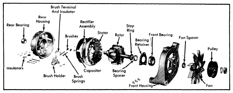 Courtesy of FORD MOTOR CO.