MOTORCRAFT DURA-Spark & Solid State Ignition: Overhaul: Distributor: Reassembly
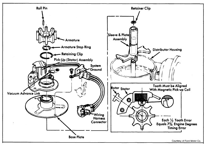
To reassemble, reverse disassembly procedure. See Fig 1. Coat brass surface of rotor with silicone grease.
| VOLTAGE TESTS |
SPECIFICATIONS |
CORRECTIONS |
| With Key On |
|
|
| Pin 4 and engine ground |
Battery Voltage ±0.1 volt |
Module Bias Test |
| Pin 1 and engine ground |
Battery Voltage ±0.1 volt |
Battery Source Test |
| While Cranking Engine |
|
|
| Pin 5 and engine ground |
8 to 12 volts |
Cranking Test |
| Jumper pin 1 to pin 8 Read voltage between coil battery terminal and ground |
More than 6 volts |
Starter Current Test |
| Pin 7 and pin 3 |
1/2 volt minimum wiggle |
Distributor Hardware Test |
 Courtesy of FORD MOTOR CO.
| RESISTANCE TESTS |
SPECIFICATIONS |
CORRECTIONS |
| With Key Off |
|
|
| Pin 7 and Pin 3 |
400 to 800 ohms |
Magnetic Pickup (Stator) Test |
| Pin 8 and engine ground |
Zero ohms |
|
| Pin 3 and engine ground |
More than 70, 000 ohms |
|
| Pin 7 and engine ground |
More than 70, 000 ohms |
|
| Pin 4 and coil tower |
7, 000 to 13, 000 ohms |
Ignition Coil Test |
| Pin 1 and coil battery terminal |
|
|
| Dura-Spark II |
1.0 to 2.0 ohms |
Ignition Coil Test |
| Dura-Spark 1 |
0.5 to 1.5 ohms |
|
| Pin 1 and engine ground |
More than 4.0 ohms |
Short Test |
| Pin 4 and coil battery terminal (Dura-Spark II Only) |
0.7 to 1.7 ohms |
Resistance Wire Test |