Front Door Switch Check
- Ensure doors are closed. Disconnect anti-theft control module 8-pin wiring harness connector. Anti-theft control module is located in right footwell below foot support. See Figure
. Ensure that wiring harness connector terminals are clean and tight.
- Connect ohmmeter between connector terminal No. "6" (Yellow/Blue wire) and ground. Insert master key in left door lock and turn clockwise. Insert master key in right door lock and turn counterclockwise. If zero ohms are present when key is in lock and held as specified, circuit is okay and testing is complete. If zero ohms are not present, go to next step.
- Ensure doors are closed. Connect ohmmeter between connector terminal No. "7" (Green/Yellow wire) and ground. Insert master key in left door lock and turn counterclockwise. Insert master key in right door lock and turn clockwise. If zero ohms are present when key is in lock and held as specified, circuit is okay and testing is complete. If zero ohms are not as present, go to next step.
- Remove connector from faulty switch. Place door latch in the closed position. Connect ohmmeter between switch terminals No. "1" and No. "3". See Fig 1
. Insert master key in left door lock and turn clockwise. Insert master key in right door lock and turn counterclockwise. If 0.5 ohm or less are present when key is in lock and held as specified, go to step 5). If more than 0.5 is present when key is in lock and held as specified, replace door switch.
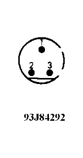 Courtesy of MERCEDES-BENZ OF NORTH AMERICA.
- With switch connector removed and door latch in the closed position, connect ohmmeter between switch terminals No. "1" and No. "2". See Fig 1
. Insert master key in left door lock and turn counterclockwise. Insert master key in right door lock and turn clockwise.
- If 0.5 ohm or less are present when key is in lock and held as specified, go to step 7). If more than 0.5 ohm is present when key is in lock and held as specified, replace door switch.
- Disconnect anti-theft control module 8-pin and 14-pin wiring harness connector (if necessary). Check for continuity between door switch connector terminal No. "1" and 14-pin connector terminal No. "2" (Brown wire) . Check for continuity between door switch connector terminal No. "2" and 8-pin connector terminal No. "7" (Green/Yellow wire).
- Check for continuity between door switch connector terminal No. "3" and 8-pin connector terminal No. "6" (Yellow/Blue wire). If continuity is not present, repair circuit as necessary. If continuity is present, circuits are okay. Replace anti-theft control module.