Back-Up Light Switch Removal/Installation
- Disconnect the negative battery cable. (See NEGATIVE BATTERY CABLE DISCONNECTION/CONNECTION
).
- Remove the parts on the cabin side.
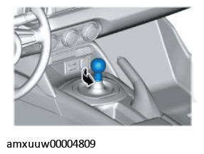
- Remove the shift lever knob.
 Courtesy of MAZDA MOTORS CORP.
- Remove the shift panel component. (See SHIFT PANEL REMOVAL/INSTALLATION
).
- Remove the upper panel. (See UPPER PANEL REMOVAL/INSTALLATION
).
- Remove the parking brake lever boot panel. (See PARKING BRAKE LEVER BOOT PANEL REMOVAL/INSTALLATION
)
- Remove the rear console. (See REAR CONSOLE REMOVAL/INSTALLATION
).
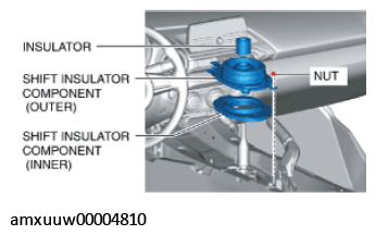
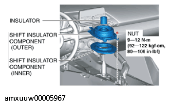
- Remove the nut, then remove the insulator and change insulator components (outer/inner).
 Courtesy of MAZDA MOTORS CORP.
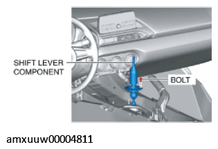
- Remove the bolt, then remove the shift lever component.
 Courtesy of MAZDA MOTORS CORP.
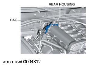
- Place a clean rag behind the engine so that the engine does not contact the rear housing when it is tilted.
 Courtesy of MAZDA MOTORS CORP.
- Remove the vehicle's underside parts.
- Remove the front crossmember under cover. (See FRONT CROSSMEMBER UNDER COVER REMOVAL/INSTALLATION
).
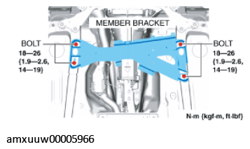
- Remove the member bracket. (With member bracket)
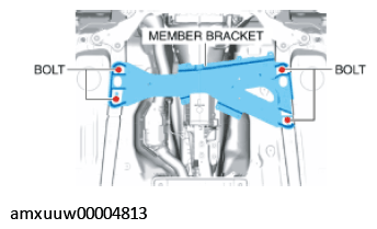 Courtesy of MAZDA MOTORS CORP.
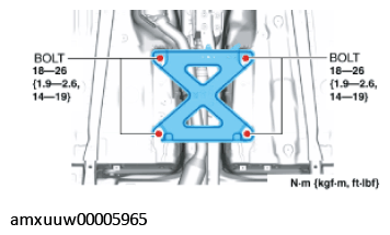
- Remove the tunnel member.
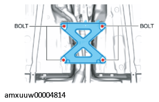 Courtesy of MAZDA MOTORS CORP.
- Detach the HO2S clip from the catalytic converter (TWC). (See HEATED OXYGEN SENSOR (HO2S) REMOVAL/INSTALLATION
).
- Disconnect the catalytic converter (TWC) from the exhaust manifold. (See EXHAUST SYSTEM REMOVAL/INSTALLATION
).
- Suspend the catalytic converter (TWC) using a cable as shown in the figure.
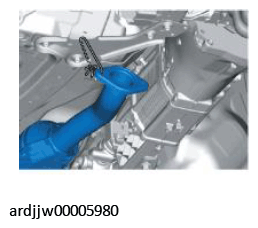 Courtesy of MAZDA MOTORS CORP.
- Remove the power plant frame. (See POWER PLANT FRAME REMOVAL ).
WARNING:
- Verify that the transmission is securely supported by a transmission jack. If the transmission falls off, it can cause serious injury or death, and damage to the vehicle.
- Tilt the transmission while being careful not to allow parts on the back of the engine to contact the vehicle body.
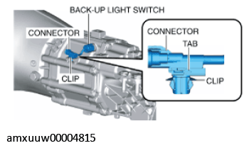
- Disconnect the back-up light switch connector.
- Detach the clip and disconnect the back-up light switch connector from the transmission.
 Courtesy of MAZDA MOTORS CORP.
- Detach the tab and remove the clip from the back-up light switch connector.
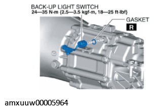
- Remove the back-up light switch.
 Courtesy of MAZDA MOTORS CORP.
- Install a new gasket and back-up light switch.
- Install the clip to the back-up light switch connector.
Courtesy of MAZDA MOTORS CORP.
- Install the back-up light switch connector to the transmission.
- Install the vehicle's underside parts.
- Install the power plant frame. (See POWER PLANT FRAME INSTALLATION ).
- Remove the tunnel member temporarily.
Courtesy of MAZDA MOTORS CORP.
- Install the catalytic converter (TWC) to the exhaust manifold. (See EXHAUST SYSTEM REMOVAL/INSTALLATION
).
- Install the HO2S clip to the catalytic converter (TWC). (See HEATED OXYGEN SENSOR (HO2S) REMOVAL/INSTALLATION
).
- Install the tunnel member.
 Courtesy of MAZDA MOTORS CORP.
- Install the member bracket. (With member bracket)
 Courtesy of MAZDA MOTORS CORP.
- Install the front crossmember under cover. (See FRONT CROSSMEMBER UNDER COVER REMOVAL/INSTALLATION
)
- Install the parts on the cabin side.
- Apply grease to the positions of the shift lever component shown in the figure.
 Courtesy of MAZDA MOTORS CORP.
- Install the shift lever component.
Courtesy of MAZDA MOTORS CORP.
- Install the insulator, change insulator components (outer/inner).
 Courtesy of MAZDA MOTORS CORP.
- Install the rear console.(See REAR CONSOLE REMOVAL/INSTALLATION
).
- Install the parking brake lever boot panel. (See PARKING BRAKE LEVER BOOT PANEL REMOVAL/INSTALLATION
).
- Install the upper panel. (See UPPER PANEL REMOVAL/INSTALLATION
).
- Install the shift panel component. (See SHIFT PANEL REMOVAL/INSTALLATION
).
- Install the shift lever knob.
Courtesy of MAZDA MOTORS CORP.
- Connect the negative battery cable. (See NEGATIVE BATTERY CABLE DISCONNECTION/CONNECTION
).