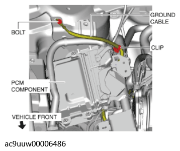
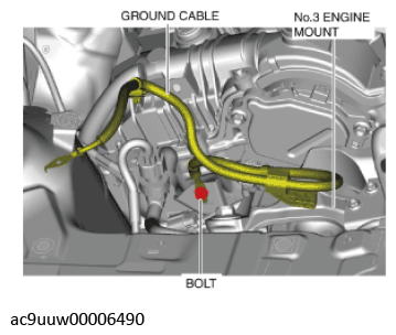
No. 3 Engine Mount Removal Note
- Remove the clip and bolt shown in the figure and set the ground cable aside.
 Courtesy of MAZDA MOTORS CORP.
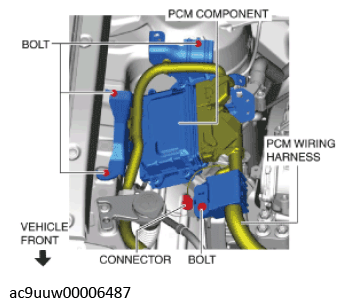
- Set the PCM component aside using the following procedure:
- Remove the bolts and connector shown in the figure.
 Courtesy of MAZDA MOTORS CORP.
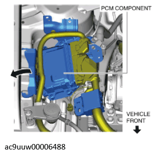
- Move the PCM component in the direction of the arrow shown in the figure and set it aside with the PCM connectors connected.
 Courtesy of MAZDA MOTORS CORP.
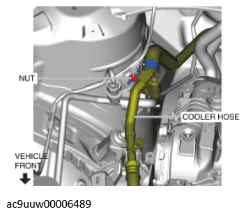
- Remove the nut shown in the figure and set the cooler hose aside.
 Courtesy of MAZDA MOTORS CORP.
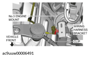
- Disconnect the ground cable shown in the figure.
 Courtesy of MAZDA MOTORS CORP.
- Disconnect the clip shown in the figure.
 Courtesy of MAZDA MOTORS CORP.
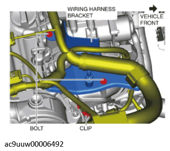
- Remove the bolts and clip shown in the figure and set the wiring harness bracket aside.
 Courtesy of MAZDA MOTORS CORP.
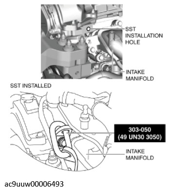
- Install the SST using part number 99794 1025 or an M10 x 1.25, length 25 mm {0.98 in} bolt as shown in the figure.
 Courtesy of MAZDA MOTORS CORP.
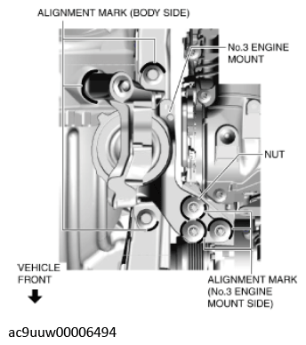
CAUTION:
- Slots have been adopted for the No. 3 engine mount installation holes. If the No. 3 engine mount is deviated from the original position when installing the No. 3 engine mount, engine noise or vibration could increase. Before removing the No. 3 engine mount, place alignment marks on the No. 3 engine mount and body so that they can be assembled to the same positions as before removal.
- Place alignment marks on the locations shown in the figure so that they can be assembled to the same positions as before removal.
 Courtesy of MAZDA MOTORS CORP.
NOTE:
- Paint so that the No. 3 engine mount is framed on the body side and the outline of the nut is framed on the No. 3 engine mount side.
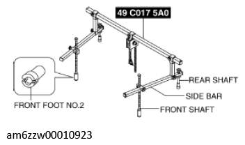
- Install the SST using the following procedures.
CAUTION:
- Refer to the
SST service instructions for the basic handing procedure.
NOTE:
- Install front foot No. 2 to the left and right front shafts of the SST.
 Courtesy of MAZDA MOTORS CORP.
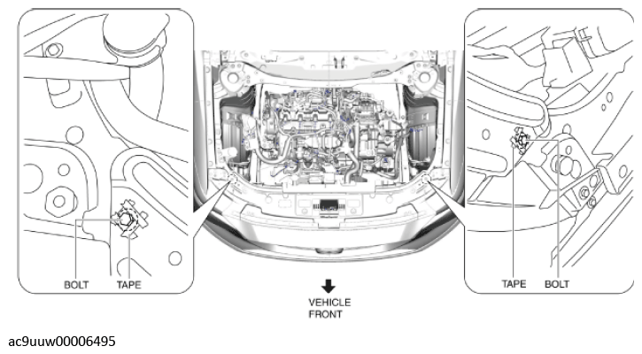
- Protect the positions shown in the figure using tape.
 Courtesy of MAZDA MOTORS CORP.
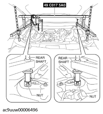
- As shown in the figure, set the rear shafts of the SST to the left and right shock absorber nuts.
 Courtesy of MAZDA MOTORS CORP.
- As shown in the figure, set the front shafts of the SST to the left and right bolts.
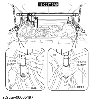 Courtesy of MAZDA MOTORS CORP.
- Adjust the height of the left and right side bars of the SST so that they are leveled, then tighten each part.
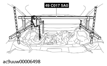 Courtesy of MAZDA MOTORS CORP.
- Apply tension to the chain to hold the engine.
- Remove the No. 3 engine mount.