Without Advanced Keyless Entry System
- Disconnect the negative battery cable. (See
NEGATIVE BATTERY CABLE DISCONNECTION/CONNECTION [SKYACTIV-G 2.0, SKYACTIV-G 2.5]
.)
- Remove the following parts:
- Liftgate upper trim (See
LIFTGATE UPPER TRIM REMOVAL/INSTALLATION
.)
- Liftgate side trim (See
LIFTGATE SIDE TRIM REMOVAL/INSTALLATION
.)
- Liftgate recess (See
LIFTGATE RECESS REMOVAL/INSTALLATION
.)
- Liftgate lower trim (See
LIFTGATE LOWER TRIM REMOVAL/INSTALLATION
.)
- Press in the latch lever of the liftgate latch and lock actuator using a flathead screwdriver, and set it to the latched condition.
 Courtesy of MAZDA MOTORS CORP.
- Install the wiring harness to the liftgate striker and the latch lever, and secure the liftgate with it half opened.
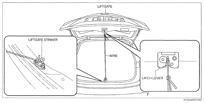 Courtesy of MAZDA MOTORS CORP.
- Remove the cap using a remover tool.
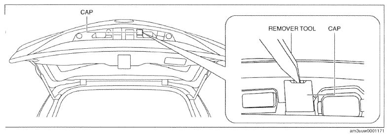 Courtesy of MAZDA MOTORS CORP.
- Remove the liftgate garnish bolt.
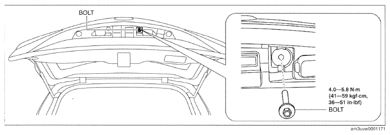 Courtesy of MAZDA MOTORS CORP.
- Remove the fasteners from the liftgate garnish in the order of the pins, guides shown in the figure.
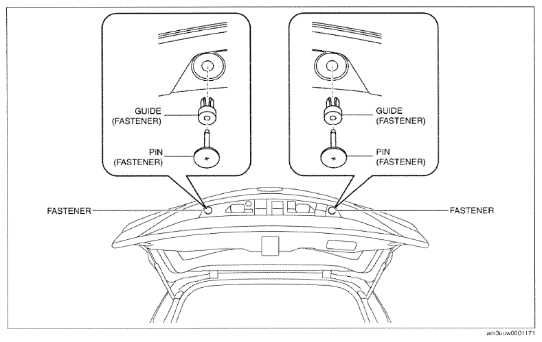 Courtesy of MAZDA MOTORS CORP.
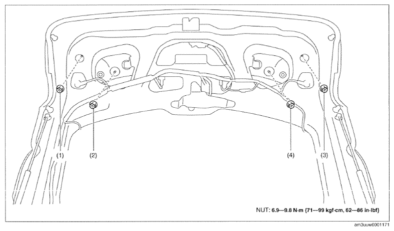
- Remove the liftgate garnish installation nuts in the order of (1), (2), (3), and (4) shown in the figure.
 Courtesy of MAZDA MOTORS CORP.
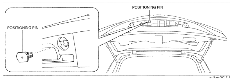
- Remove the positioning pin from the liftgate garnish.
 Courtesy of MAZDA MOTORS CORP.
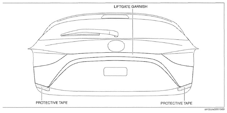
- Adhere protective tape to the area shown in the figure.
 Courtesy of MAZDA MOTORS CORP.
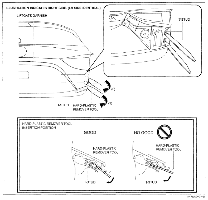
- Insert the hard-plastic remover tool in the position shown in the figure.
 Courtesy of MAZDA MOTORS CORP.
- Move the hard-plastic remover tool in the direction of the arrow shown in the figure and disengage the liftgate garnish clips from the T-studs on the liftgate side in the order of (1) and (2).
CAUTION:
- When disengaging the T-studs, always use a hard-plastic remover tool being careful not to apply surplus load to the T-studs. If the flathead screwdriver is used when disengaging the T-studs, the T-stud unit installed on the liftgate side may be damaged.
- Insert a flathead screwdriver wrapped in protective tape into the positions shown in the figure as far as the clip root.
NOTE:
- To facilitate the procedure, insert the remover tool into the gap between the liftgate and the liftgate garnish and visually verify the clip positions.
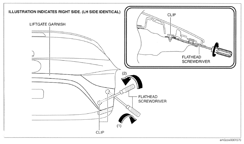 Courtesy of MAZDA MOTORS CORP.
- Rotate the flathead screwdriver wrapped in protective tape in the direction of the arrows shown in the figure and disengage the liftgate garnish clips from the liftgate in the order of (1) and (2).
CAUTION:
- If a clip being installed to the liftgate is damaged and left installed to the vehicle, it could cause abnormal noise. If a clip Installed to the liftgate garnish has been damaged, remove it and replace it with a new one.
- Always detach the liftgate garnish clips with at least one other person holding the liftgate garnish. Otherwise, the liftgate garnish may fall and damage the vehicle body.
- Remove the liftgate garnish.
- Install in the reverse order removal.