| POSSIBLE CAUSES |
- unable to communicate with powertrain control module (PCM)
- incorrect self-test procedure
- harness circuits: ISP-R, PCMRC, PWRGND and VPWR
|
 Courtesy of MAZDA MOTORS CORP. Courtesy of MAZDA MOTORS CORP.
|
| STEP |
INSPECTION |
ACTION |
| 1 |
CARRY OUT A VEHICLE INSPECTION AND VERIFY THE SELF-TEST PROCEDURE
NOTE:
- If the self-test or communication concern occurred after a failed or an aborted reprogram, the module may be blank. Attempt to reprogram the module again before continuing with this pinpoint test.
- Visually inspect the following for obvious signs of electrical damage:
- harness wiring
- electrical connections
- Verify the correct procedure was used to activate the self-test for the scan tool.
- Was the correct self-test procedure used?
|
Yes |
GO to the next step. |
| No |
Set up scan tool. |
 Courtesy of MAZDA MOTORS CORP. Courtesy of MAZDA MOTORS CORP.
|
| 2 |
CARRY OUT THE NETWORK TEST
NOTE:
- When using Integrated Diagnostic System (IDS), the scan tool attempts to communicate with the PCM first. After establishing communication with the PCM, the scan tool then attempts to communicate with all modules on the vehicle. If an IDS session cannot be established, IDS may state no communication can be established with the PCM:
- Choose No when the scan tool prompts whether or not to retry communication.
- Enter a PCM part number, tear tag or calibration number to identify the vehicle and start a session. The PCM part number and 4-character tear tag are located on the PCM.
- Key ON, engine OFF.
- Carry out the network test.
- Do all modules indicate pass?
|
Yes |
GO to the next step. |
| No |
If only PCM indicates fail, GO to the next step.
For network test or all other modules indicates fail, COMMUNICATIONS NETWORK - TROUBLESHOOTING 09-01H-4 to diagnose The Powertrain Control Module (PCM) Does Not Respond To The Scan Tool Or No High Speed Controller Area Network (HS-CAN) Communication Symptom. |
Courtesy of MAZDA MOTORS CORP.
|
| 3 |
CHECK FOR VREF VOLTAGE AT A SENSOR
- Key ON, engine OFF.
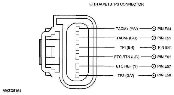
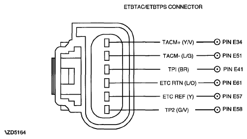
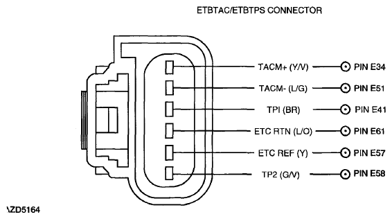
- For electronic throttle control (ETC) applications, ETBTPS connector disconnected.
- Measure the voltage between:
- (+) ETBTPS Connector ETCREF, Harness Side
- (+) ETBTPS Connector ETCRTN, Harness Side
- Is the voltage between 4.5 - 5.5 V?
|
Yes |
See COMMUNICATIONS NETWORK - TROUBLESHOOTING
to diagnose The Powertrain Control Module (PCM) Does Not Respond To The Scan Tool Or No High Speed Controller Area Network (HS-CAN) Communication Symptom. |
| No |
GO to the next step. |
| 4 |
CHECK THE ISP-R VOLTAGE AT THE PCM HARNESS CONNECTOR
- Key OFF.
- PCM connector disconnected.
- Key ON, engine OFF.
- Measure the voltage between (+) PCM Connector ISP-R, Harness Side and (-) 12 Volt Vehicle Battery, Negative terminal
- While observing the multimeter, grasp the EEC harness and wiggle, shake or bend a small area while working from the battery to the PCM.
- Is the voltage greater than 10 V?
|
Yes |
GO to the next step. |
| No |
REPAIR the open circuit. CLEAR the DTCs. REPEAT the self-test. |
 Courtesy of MAZDA MOTORS CORP. Courtesy of MAZDA MOTORS CORP.
|
| 5 |
CHECK THE PCM VPWR CIRCUITS FOR VOLTAGE
- Key in OFF position.
- Disconnect the PCM.
- Connect a 5 amp fused jumper wire between the following:
- Point A PCM Connector PCMRC, Harness Side
- Point B PCM Connector, Ground
- Key ON, engine OFF.
- Measure the voltage between:
- (+) PCM Connector VPWR, Harness Side
- (-) Ground
- Are the voltages greater than 10 V?
|
Yes |
GO to the next step. |
| No |
See TEST 6: PCM POWER RELAY
. |
| 6 |
CHECK THE PCM VPWR CIRCUITS FOR VOLTAGE
- Key in OFF position.
- Disconnect the PCM.
- Key ON, engine OFF.
- Measure the voltage between:
- (+) PCM Connector VPWR, Harness Side
- (-) Ground
- Is the voltage greater than 10 V?
|
Yes |
GO to the next step. |
| No |
See TEST 6: PCM POWER RELAY
. |
Courtesy of MAZDA MOTORS CORP.
|
| 7 |
CHECK THE PCM GROUND CIRCUITS FOR AN OPEN
- Key in OFF position.
- Measure the resistance between:
- (+) PCM Connector PWRGND, Harness Side
- (-) Ground
- Are the resistances less than 5 ohms??
|
Yes |
GO to the next step. |
| No |
REPAIR the open circuit. CLEAR the DTCs. REPEAT the self-test. |
| 8 |
VERIFY TROUBLESHOOTING OF DTCs COMPLETED
- Disconnect all the PCM connectors.
- Check for:
- corrosion
- damaged pins
- pushed-out pins
- Connect all connectors and make sure they seat correctly.
- Clear DTCs from PCM memory using IDS or equivalent generic OBD II tester.
- Carry out the PCM Quick Test. See PCM QUICK TEST
.
- Is the same DTC present?
|
Yes |
INSTALL a new PCM.
See POWERTRAIN CONTROL MODULE (PCM) REMOVAL/INSTALLATION - 2.5L
or POWERTRAIN CONTROL MODULE (PCM) REMOVAL/INSTALLATION - 3.0L
.
REPEAT the PCM Quick Test. See PCM QUICK TEST
. |
| No |
If any other DTC is present, go to applicable DTC inspection.
If no DTC is present, troubleshooting complete. |