Input Signal System Investigation Procedure: VSS
 Courtesy of MAZDA MOTORS CORP.
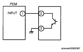
- Measure the #1 PCM terminal voltage and confirm that it is at 0 V
or 5 V
when the ignition switch to the ON position and the engine is idling.
- If it is at 0 V
or 5 V
, intermittent concern exists. (See
INTERMITTENT CONCERN TROUBLESHOOTING .)
- If not, inspect the following points concerning the PCM connector.
- If there is no problem, inspect for the following:
- Female terminal opening is loose.
- Coupler (pin holder) damage
- Pin discoloration (blackness)
- Wiring harness/pin crimp is loose or disconnected.
- Measure the #2 sensor terminal voltage and confirm that it is at 0 V
or 5 V
when the ignition switch to the ON position and the engine is idling.
- If it is at 0 V
or 5 V
, intermittent concern exists. (See
INTERMITTENT CONCERN TROUBLESHOOTING .)
- If not, inspect the following points concerning the sensor connector:
- If there is no problem, inspect for the following.
- Female terminal opening is loose.
- Coupler (pin holder) damage
- Pin discoloration (blackness)
- Wiring harness/pin crimp is loose or disconnected.
- Confirm that the #3 terminal switch voltage is at 0 V
.
- If it is at 0 V
, inspect the sensor. If necessary, replace the sensor.
- If necessary, replace the sensor.
- If not, inspect for the following:
- Open circuit in wiring harness
- Female terminal opening is loose.
- Coupler (pin holder) damage
- Pin discoloration (blackness)
- Wiring harness/pin crimp is loose or disconnected.