Transaxle - 2.3L: Removal
- With the vehicle in NEUTRAL, position it on a hoist. See
LIFTING
.
 Courtesy of MAZDA MOTORS CORP.
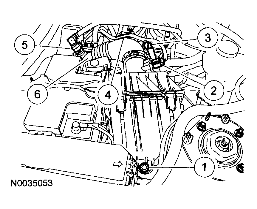
- Remove the air cleaner as an assembly.
- Remove the bolt.
- Disconnect the mass air flow (MAF) sensor electrical connector.
- Disconnect the brake booster vacuum hose.
- Disconnect the wiring harness retainer.
- Disconnect the breather tube.
- Loosen the clamp and remove the air cleaner assembly.
- Remove the battery and the battery tray. See
BATTERY TRAY - 2.3L
.
 Courtesy of MAZDA MOTORS CORP.
- Disconnect the power takeoff (PTO) vent hose from the clip located on the fill tube.
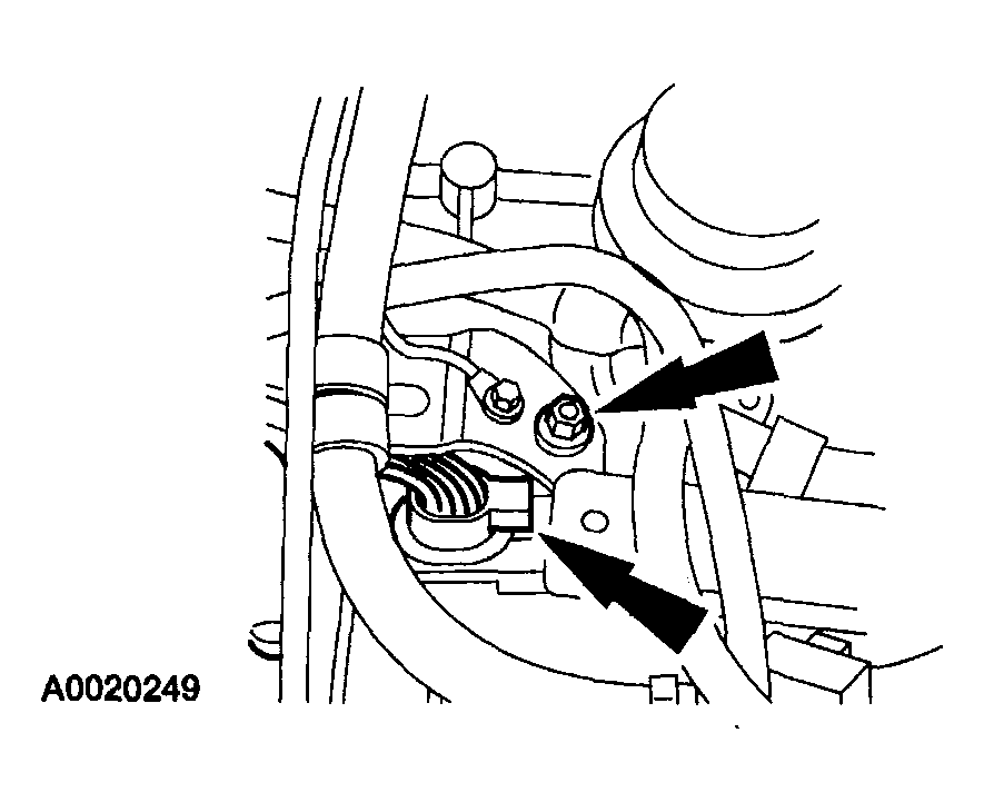 Courtesy of MAZDA MOTORS CORP.
- Remove the three bolts holding the shift cable bracket and ground wires and unplug the transaxle electrical connector.
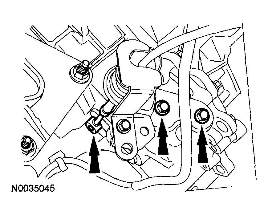 Courtesy of MAZDA MOTORS CORP.
- Remove two bolts from the shift cable bracket and disconnect the shift cable from the transaxle manual lever.
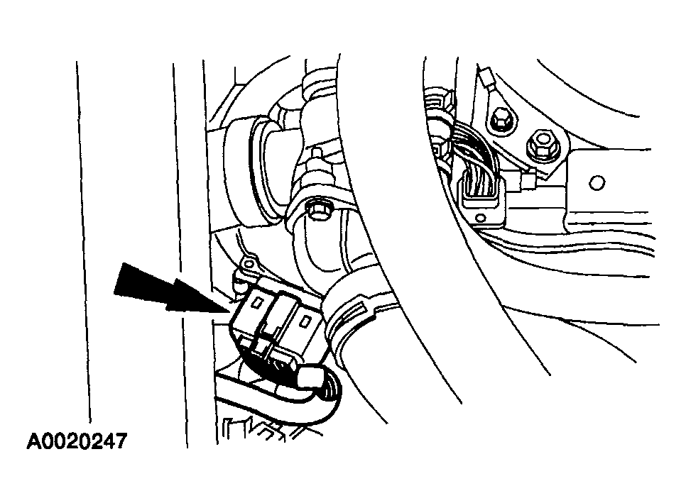 Courtesy of MAZDA MOTORS CORP.
- Disconnect the transaxle range (TR) sensor electrical connector.
 Courtesy of MAZDA MOTORS CORP.
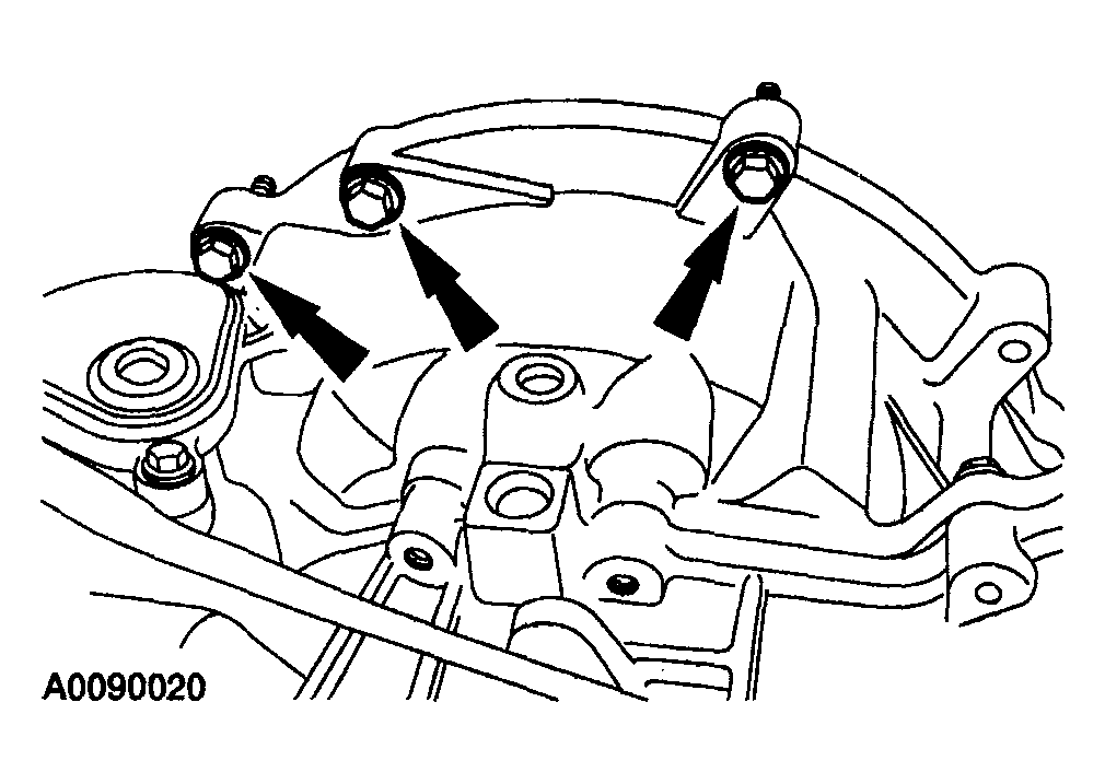
- Remove the three upper transaxle retaining bolts.
 Courtesy of MAZDA MOTORS CORP.
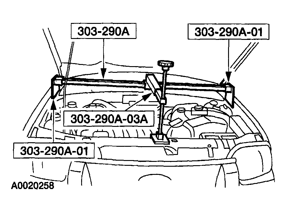
- Install the special tools.
 Courtesy of MAZDA MOTORS CORP.
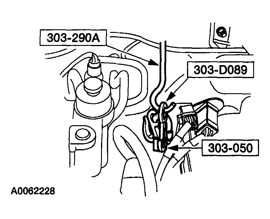
- Install the special tools.
 Courtesy of MAZDA MOTORS CORP.
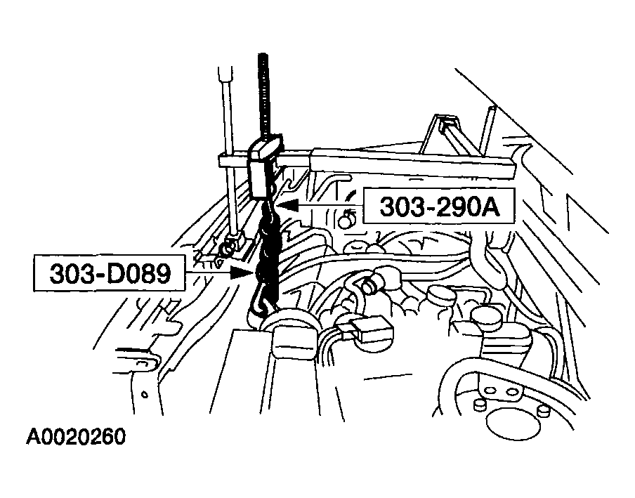
- Install the special tools.
 Courtesy of MAZDA MOTORS CORP.
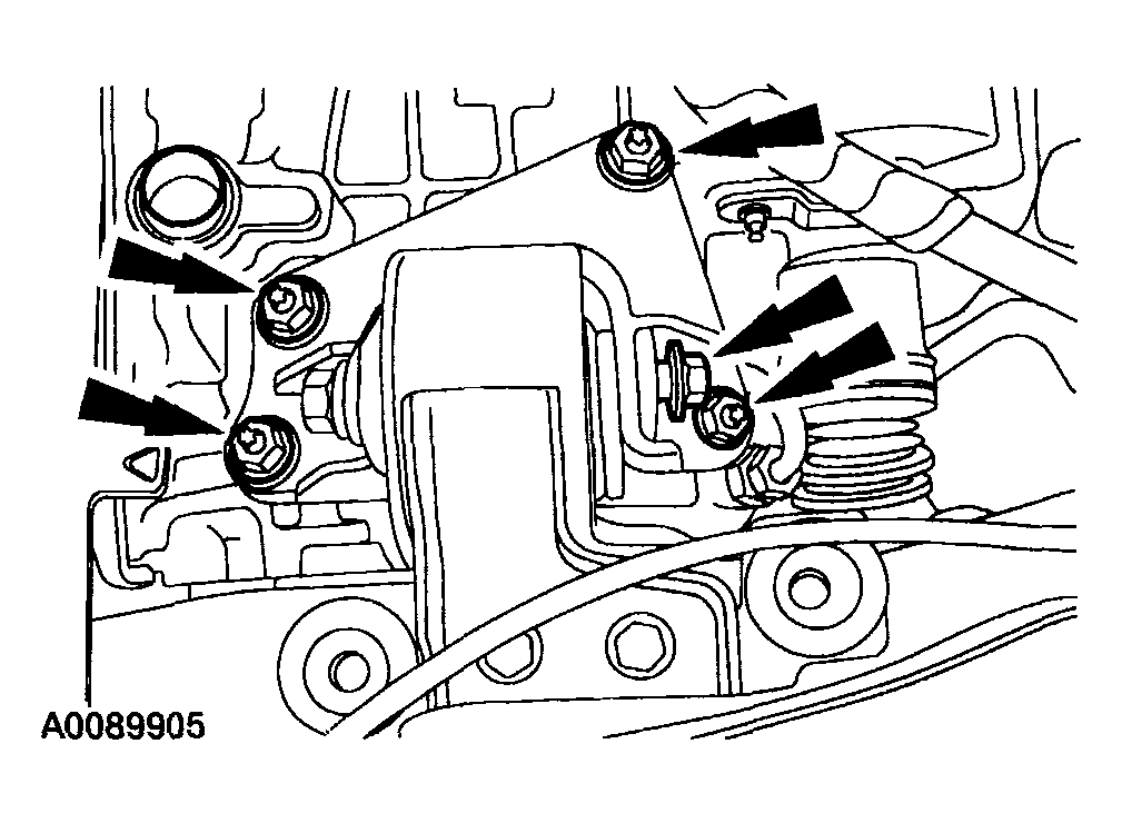
- Loosen but do not remove the four retaining nuts holding the bracket to the transaxle case. Remove the LH upper transaxle mount bolt.
 Courtesy of MAZDA MOTORS CORP.
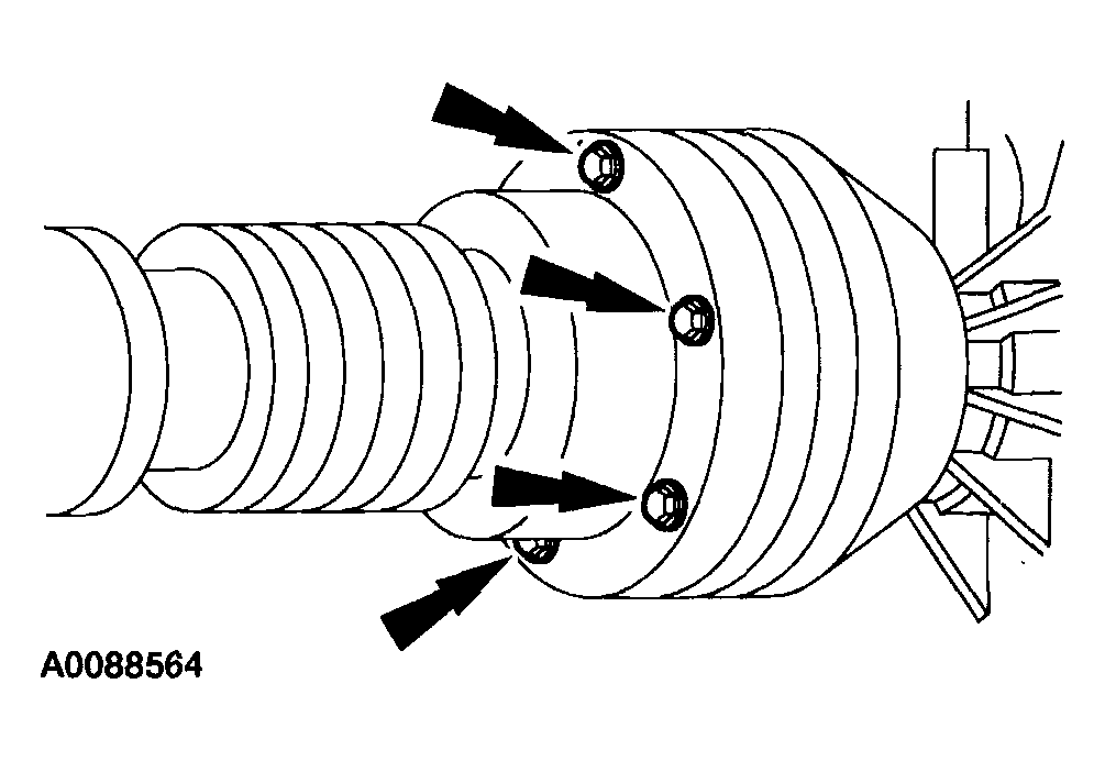
- Remove the six bolts holding the driveshaft to the PTO.
 Courtesy of MAZDA MOTORS CORP.
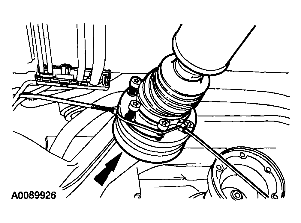
- Position the driveshaft aside.
 Courtesy of MAZDA MOTORS CORP.
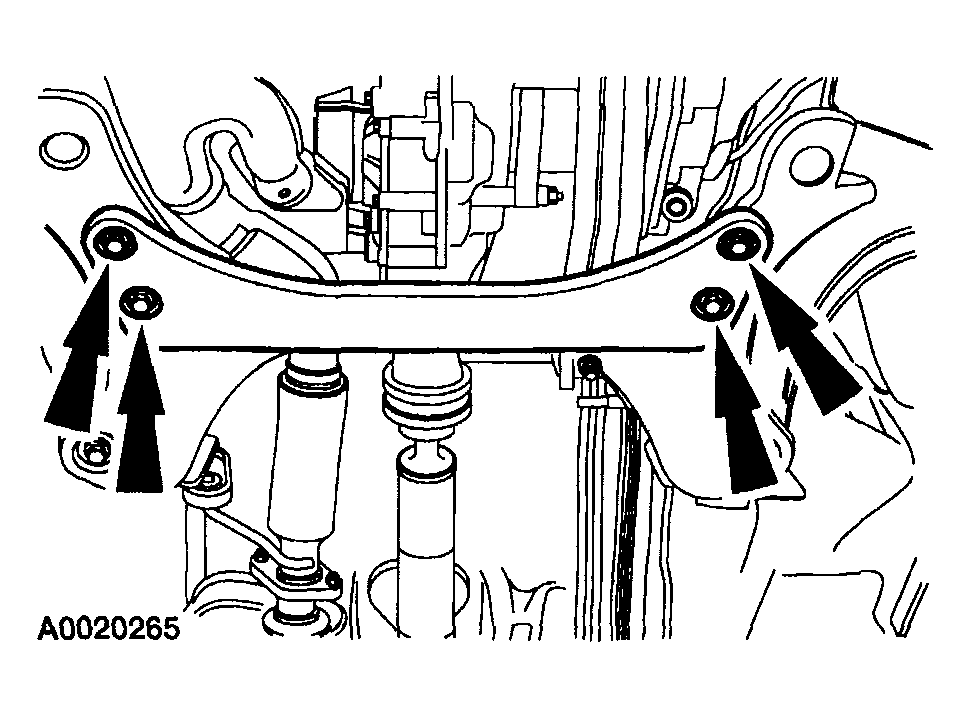
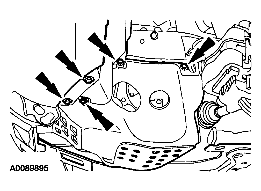
- Remove the four bolts and remove the cross brace.
 Courtesy of MAZDA MOTORS CORP.
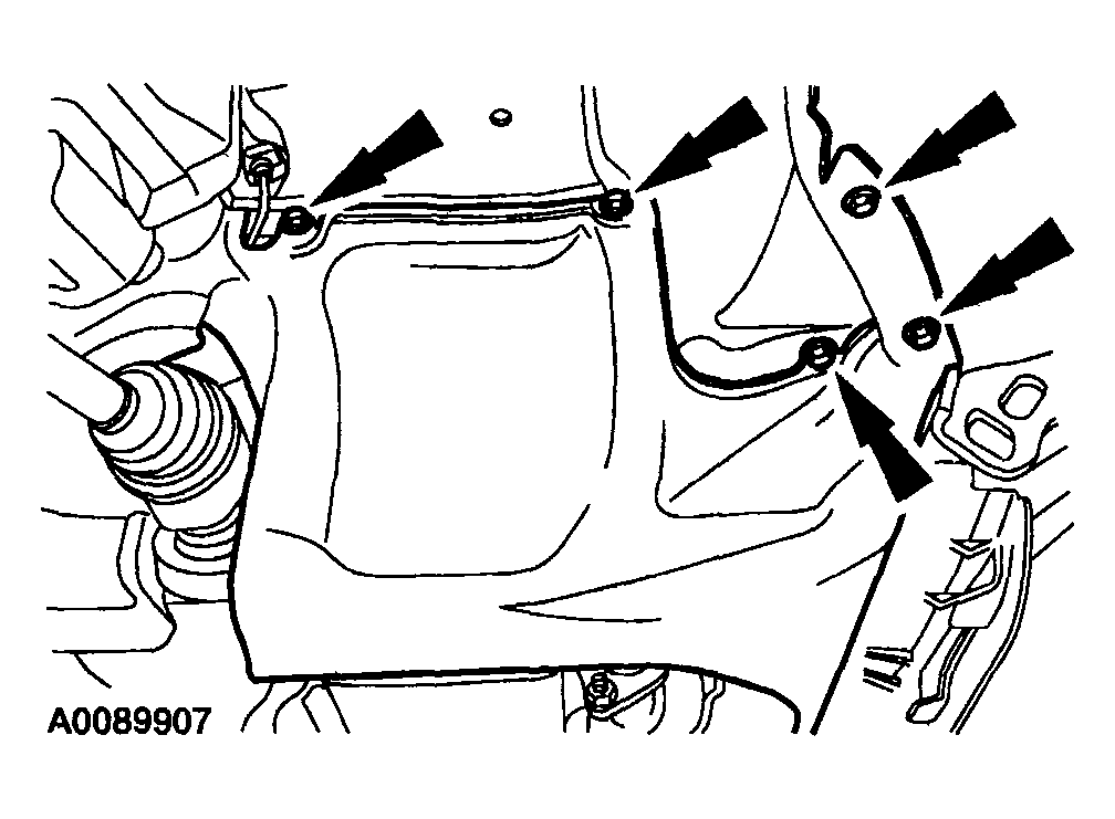
- Remove the seven retainers and the LH splash shields.
 Courtesy of MAZDA MOTORS CORP.
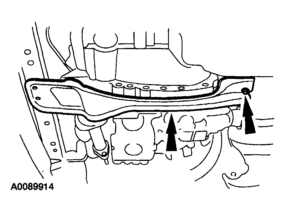
- Remove the seven retainers and the RH splash shield.
 Courtesy of MAZDA MOTORS CORP.
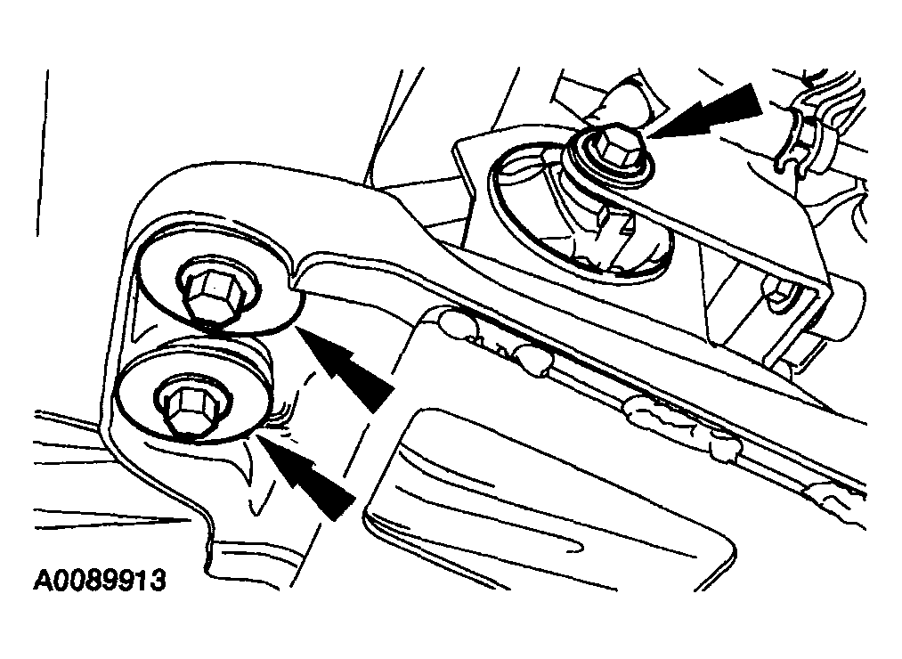
- Remove the bolt for the mount and the two bolts for the cross brace.
 Courtesy of MAZDA MOTORS CORP.
- Remove the rear nut and the cross brace.
 Courtesy of MAZDA MOTORS CORP.
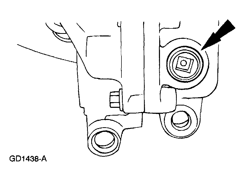
- Remove the drain plug and drain the fluid.
 Courtesy of MAZDA MOTORS CORP.
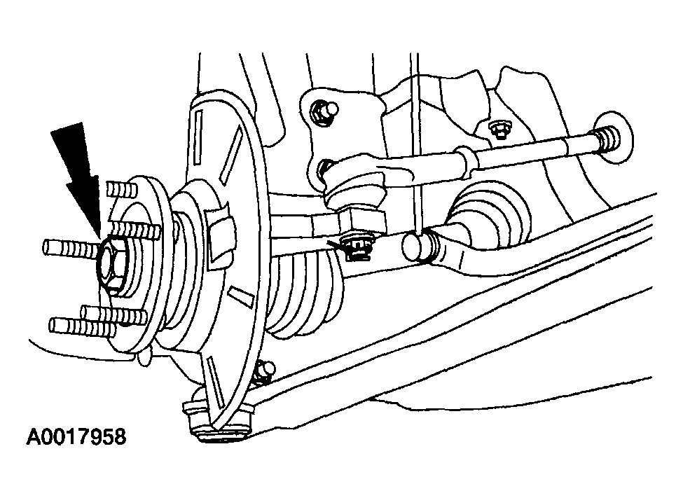
- Remove and discard the LH front axle wheel hub nut.
 Courtesy of MAZDA MOTORS CORP.
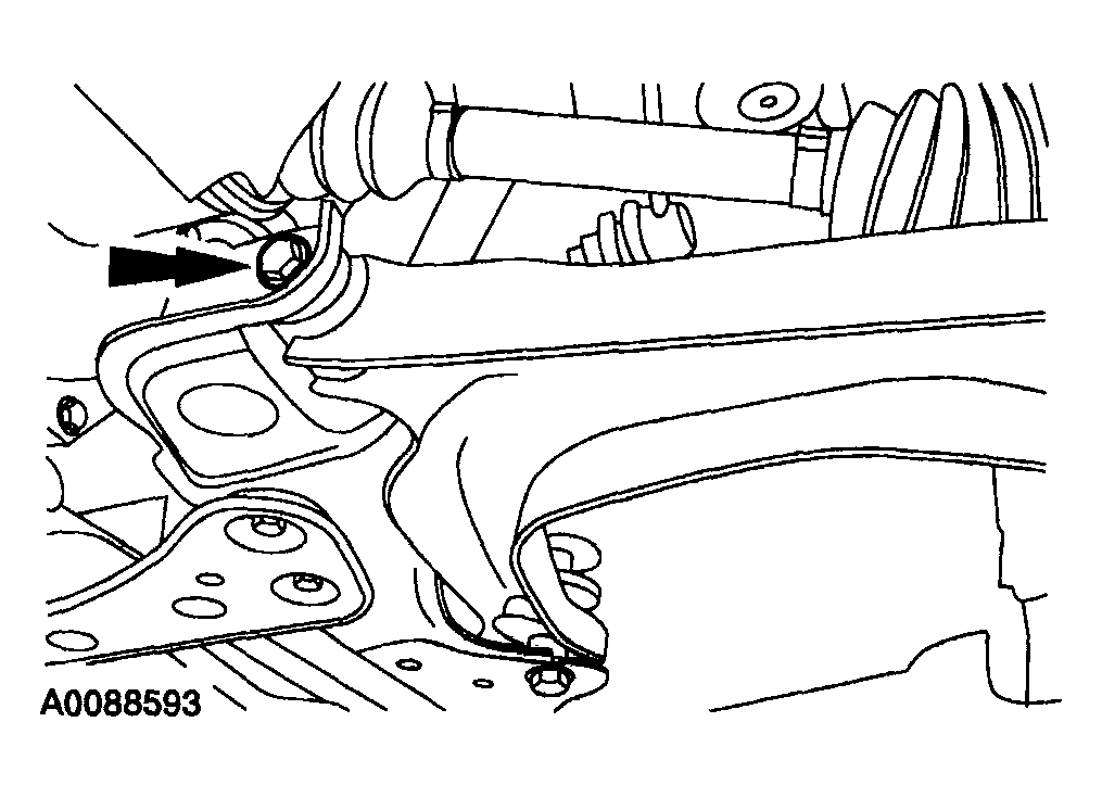
- Remove the frame bolt from the LH and RH control arms.
 Courtesy of MAZDA MOTORS CORP.
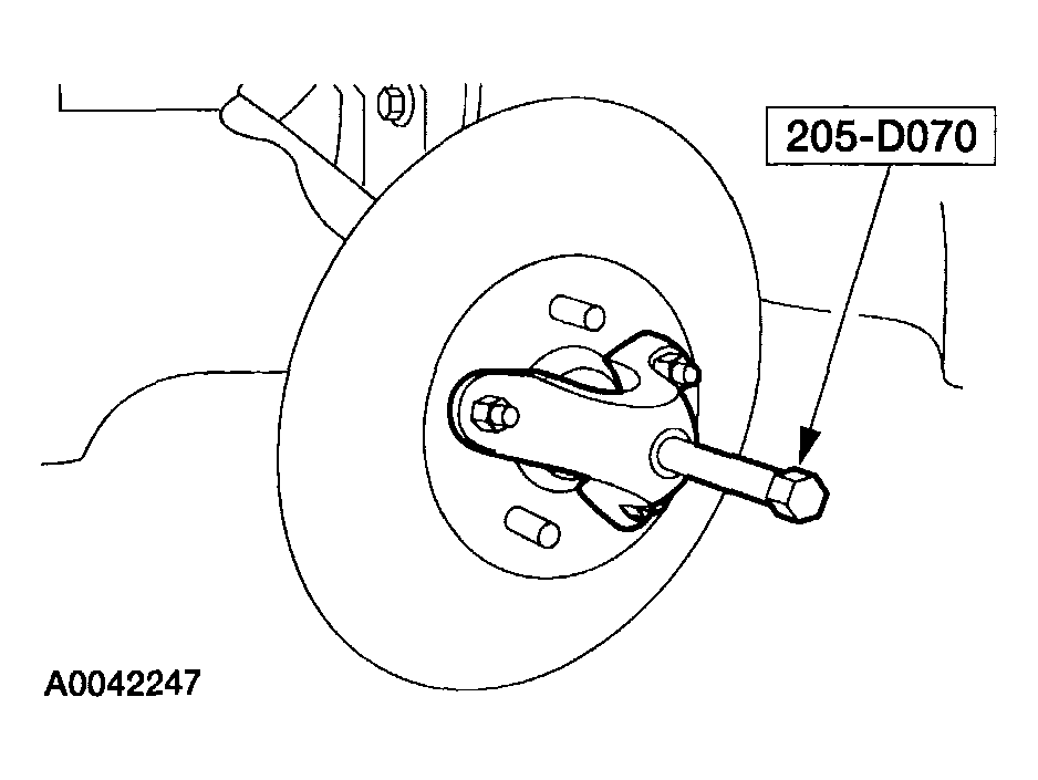
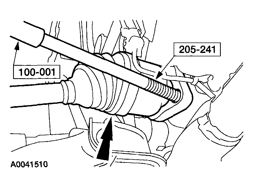
- Using the special tool, separate the LH halfshaft from the front wheel knuckle.
 Courtesy of MAZDA MOTORS CORP.
- Using the special tools, remove the LH and RH half-shaft.
 Courtesy of MAZDA MOTORS CORP.
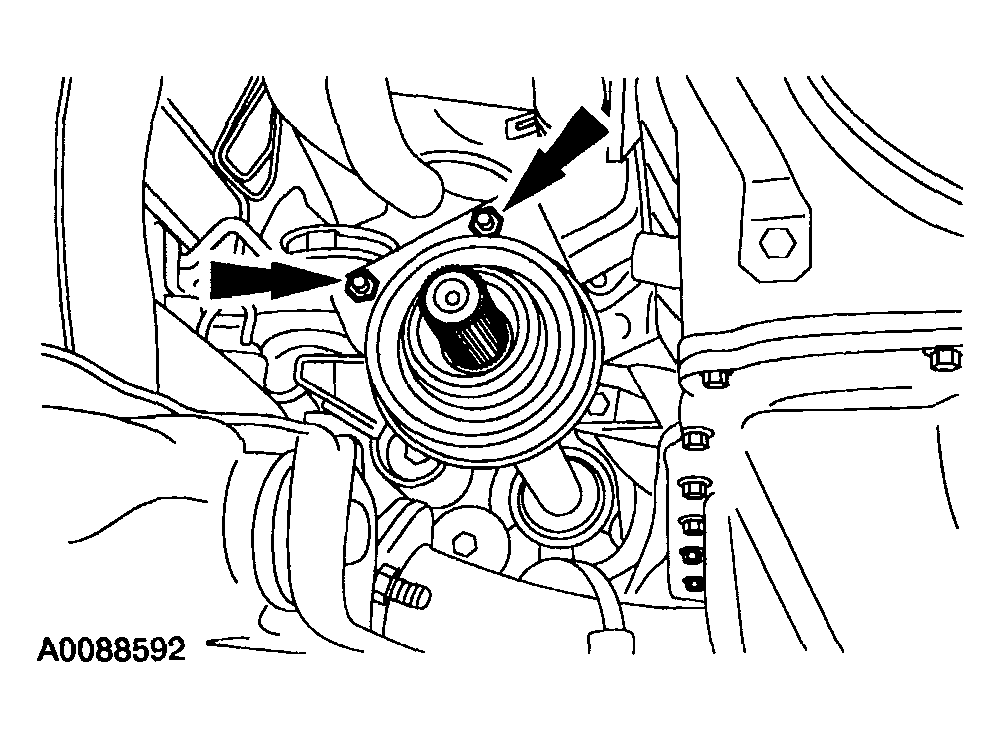
- Remove the two intermediate shaft retaining nuts.
 Courtesy of MAZDA MOTORS CORP.
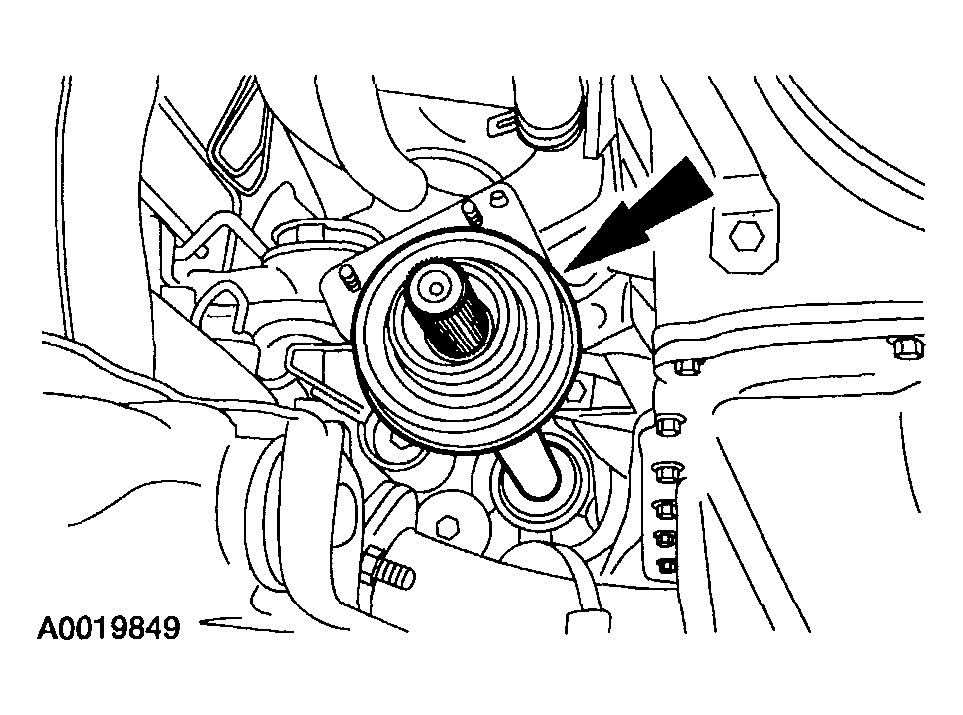
- Remove the intermediate shaft.
 Courtesy of MAZDA MOTORS CORP.
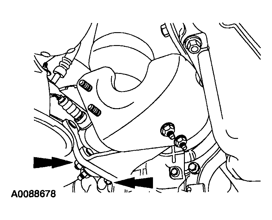
- Remove the two nuts which hold the exhaust bracket to the rear engine mount.
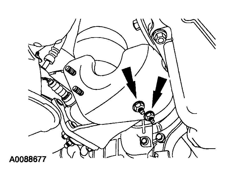 Courtesy of MAZDA MOTORS CORP.
- Remove the two nuts and bolts on the other end of the exhaust-to-rear engine mount bracket and remove the bracket.
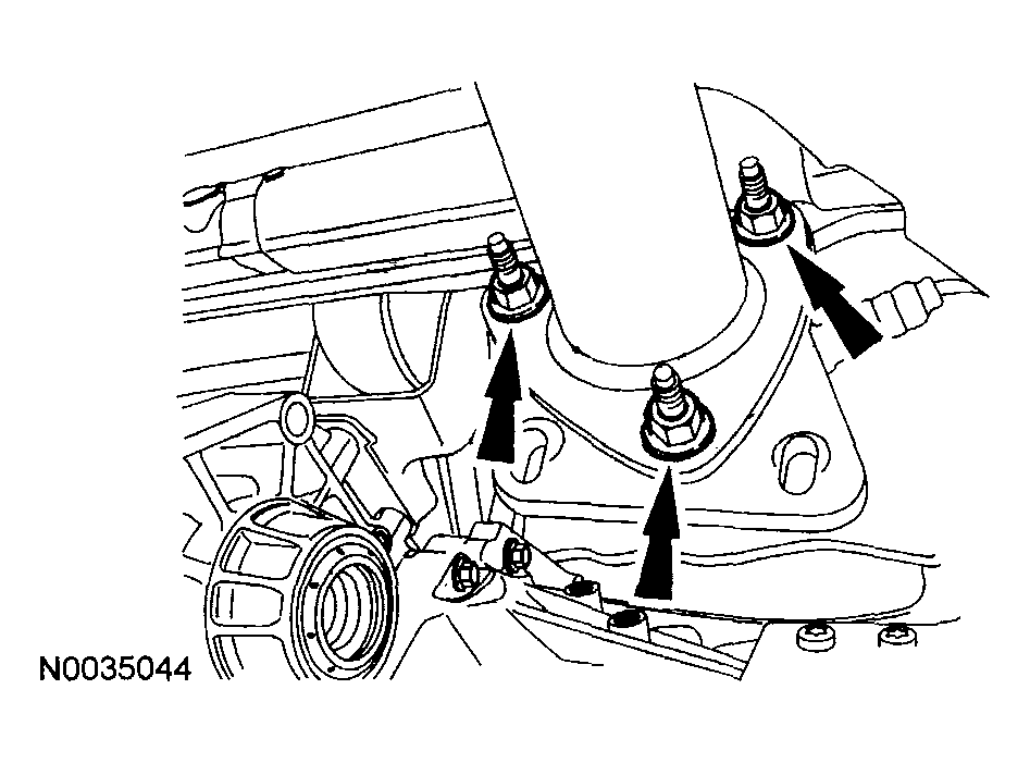 Courtesy of MAZDA MOTORS CORP.
- Remove the three nuts and separate the flexpipe from the exhaust manifold.
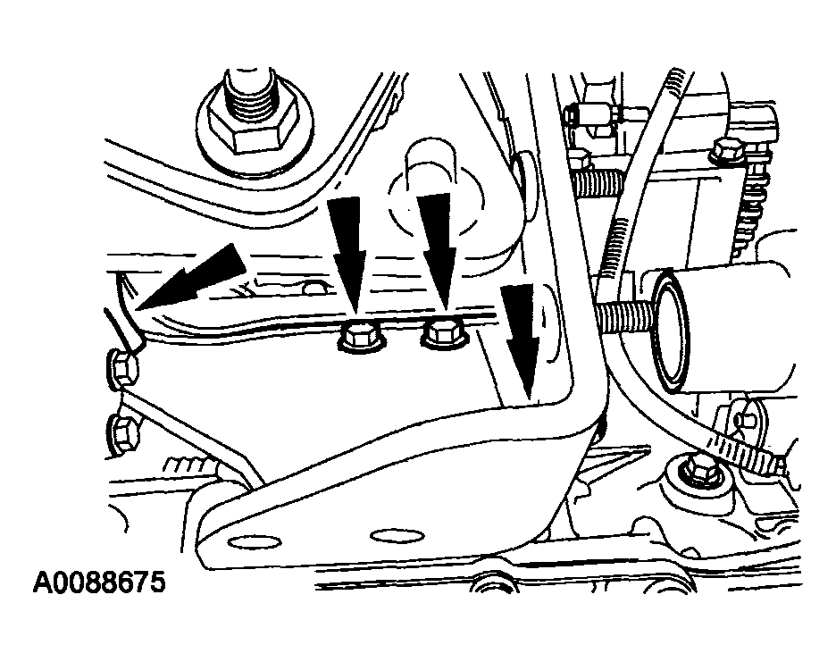 Courtesy of MAZDA MOTORS CORP.
- Remove the six bolts holding the engine bracket to the PTO and remove the bracket.
- For vehicles that are not equipped with a PTO, remove the dampener.
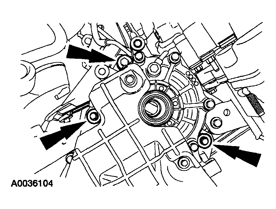 Courtesy of MAZDA MOTORS CORP.
- Remove the three bolts and the PTO assembly.
 Courtesy of MAZDA MOTORS CORP.
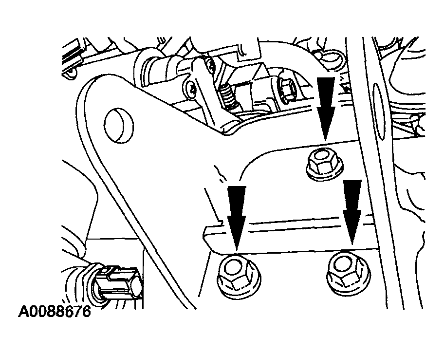
- Remove the three bolts holding the transaxle front mount plate.
 Courtesy of MAZDA MOTORS CORP.
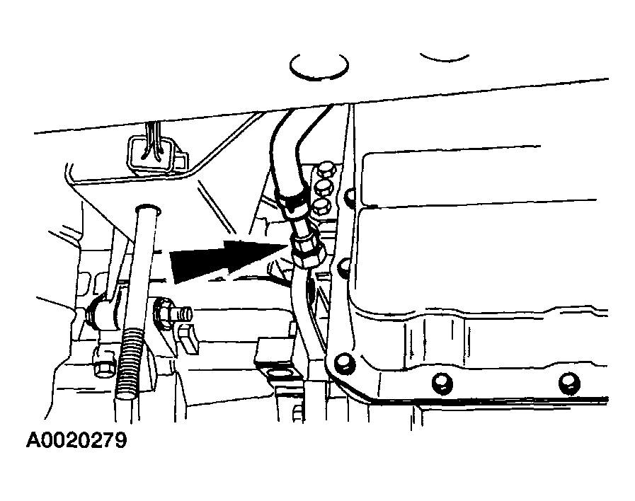
- Remove the fluid cooler line.
 Courtesy of MAZDA MOTORS CORP.
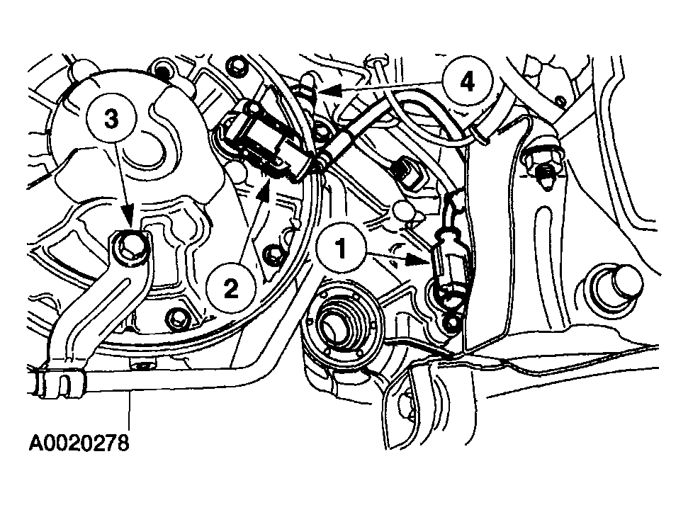
- Remove the fluid cooler tube.
- Disconnect the output shaft speed (OSS) sensor electrical connector (black).
- Disconnect the turbine shaft speed (TSS) sensor electrical connector (white connector).
- Remove the transaxle fluid cooler retaining bracket bolt.
- Remove the fluid cooler tube and position it aside.
 Courtesy of MAZDA MOTORS CORP.
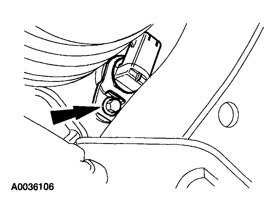
- Remove the OSS sensor.
 Courtesy of MAZDA MOTORS CORP.
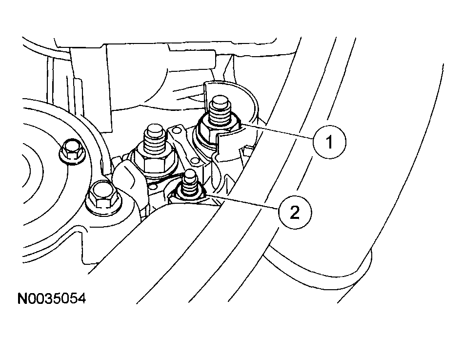
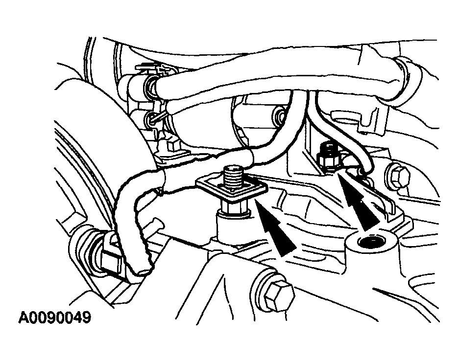
- Disconnect the starter terminals.
- Remove the battery cable nut.
- Remove the starter solenoid terminal nut.
 Courtesy of MAZDA MOTORS CORP.
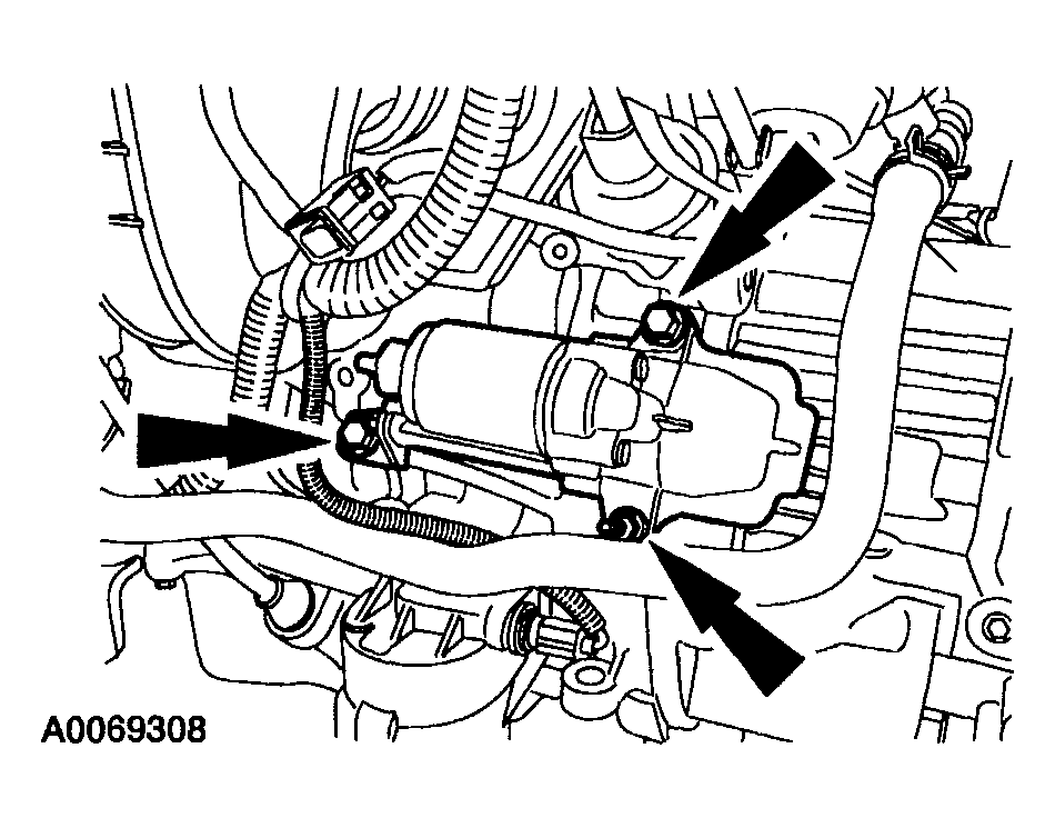
- Remove the wire harness clip retainer and the ground wire from the starter bolts.
 Courtesy of MAZDA MOTORS CORP.
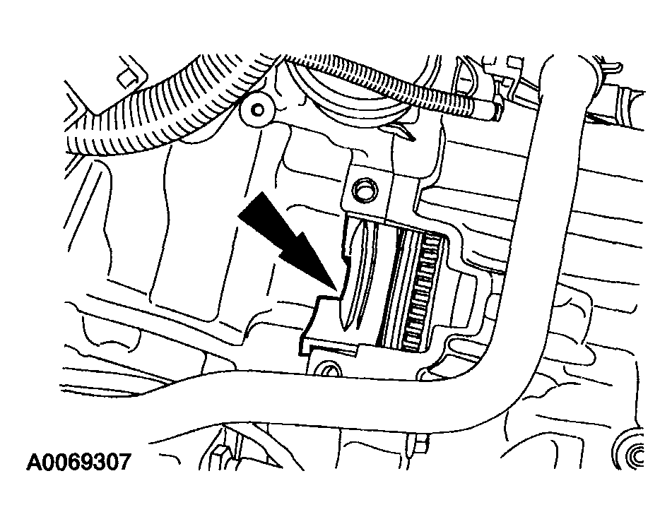
- Remove the three bolts and remove the starter.
 Courtesy of MAZDA MOTORS CORP.
- Remove the starter motor isolator.
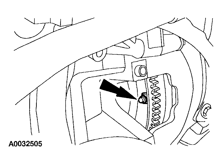 Courtesy of MAZDA MOTORS CORP.
- Remove and discard the four torque converter nuts.
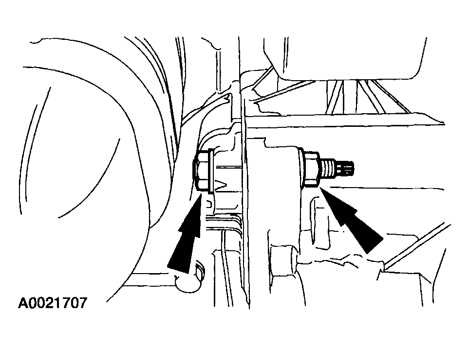 Courtesy of MAZDA MOTORS CORP.
- Push the converter back from the flexplate. Use a suitable transaxle jack to support the transaxle and remove the bolt from the lower front case.
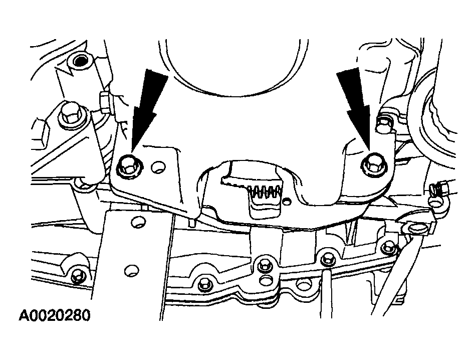 Courtesy of MAZDA MOTORS CORP.
- Remove the four remaining transaxle-to-engine bolts.
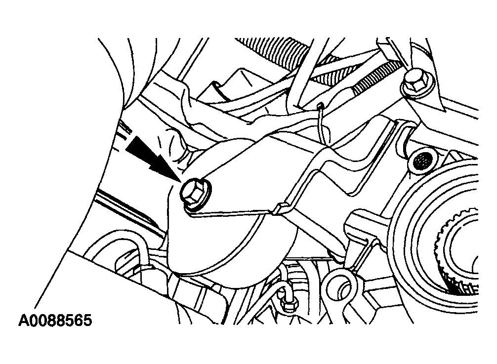 Courtesy of MAZDA MOTORS CORP.
- Remove the bolt from the transaxle rear mount.
 Courtesy of MAZDA MOTORS CORP.
CAUTION:
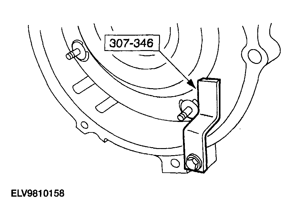
- The torque converter is heavy. Install the special tool before lowering the transaxle.
- Move the transaxle back far enough to install the special tool.
 Courtesy of MAZDA MOTORS CORP.
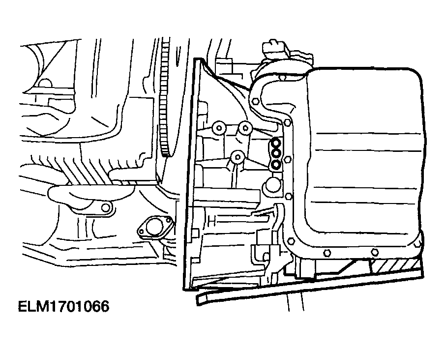
- Lower the transaxle from the engine compartment.