Knock Sensor Malfunction
DTC P0325, P0326, P0327, P0328, P0329 DETECTION CONDITION AND POSSIBLE CAUSES
| DTC P0325, P0326, P0327, P0328, P0329 |
KNOCK SENSOR MALFUNCTION |
| DETECTION CONDITION |
- P0325 indicates a knock sensor circuit malfunction.
- P0326 - P0329 indicate a knock sensor has detected vibrations (voltage generated based on this vibration) upon an increase and decrease in engine rpm that is outside a calibrated level.
|
| POSSIBLE CAUSE |
- Knock sensor circuit short to GND.
- Knock sensor circuit short to PWR.
- Open knock sensor circuit.
- Damaged knock sensor.
- Damaged PCM.
|
| HINT |
Knock Sensor Description
- A tuned accelerometer on the engine that converts engine vibration to an electrical signal.
- The PCM uses this signal to determine the presence of engine knock and retard spark timing if necessary.
|
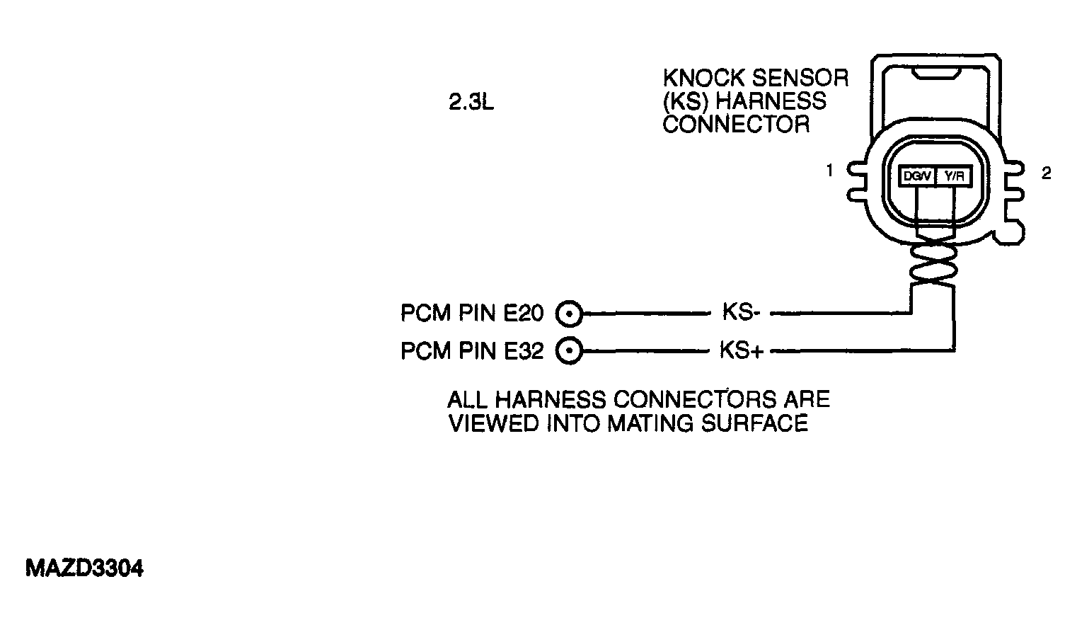 Courtesy of MAZDA MOTORS CORP.
|
DTC P0325, P0326, P0327, P0328, P0329 DIAGNOSTIC PROCEDURE
| STEP |
INSPECTION |
ACTION |
| 1 |
- Was PCM Quick Test performed?
|
Yes |
Go to next step. |
| No |
Perform PCM Quick Test. See
PCM QUICK TEST
. |
| 2 |
CHECK VOLTAGE BETWEEN SENSOR AND SIG RTN
- Verify KS sensor is installed properly and connector is connected.
- Complete the repair verification drive cycle. See
DRIVE CYCLE
.
- Key ON, Engine OFF (KOEO).
- Access KSI PID.
- Is KSI PID less than 0.5 volts?
|
Yes |
Key OFF.
Go to next step. |
| No |
Go to step 6. |
| 3 |
CHECK KS SENSOR RESISTANCE
- Disconnect PCM.
- Install Breakout Box, leave PCM disconnected.
- Measure the resistance between PCM test pin E20 and PCM test pin E32.
- Is the resistance between 4.39 and 5.35 mega ohms?
|
Yes |
Go to step 7. |
| No |
For resistances greater than 5.35 mega ohms, go to next step.
For resistances less than 4.39 mega ohms, go to step 5. |
| 4 |
CHECK FOR OPEN OF KS+ CIRCUIT
- Disconnect KS sensor.
- Measure the resistance of KS+ circuit between PCM test pin E32 and the KS pin 2, circuit (Y/R).
- Is the resistance less than 5.0 ohms?
|
Yes |
Replace KS sensor, See
KNOCK SENSOR (KS) - 2.3L
.
Go to step 8. |
| No |
Repair open circuit.
Go to step 8. |
| 5 |
CHECK KS+ CIRCUIT FOR SHORT TO GROUND IN HARNESS
- Measure the resistance of KS+ circuit between PCM test pin E32 and chassis ground.
- Measure the resistance of KS-circuit between PCM test pin E20 and chassis ground.
- Is the resistance greater than 10K ohms?
|
Yes |
Go to next step. |
| No |
Repair short circuit.
Go to step 8. |
| 6 |
CHECK KS CIRCUITS FOR SHORT TO POWER IN HARNESS
- Connect PCM to Breakout Box.
- Key ON, Engine OFF (KOEO).
- Measure the voltage of KS+ circuit between PCM test pin E32 and battery negative post.
- Measure the voltage of KS-circuit between PCM test pin E20 and battery negative post.
- Was bias voltage reading less than 1.0 V?
|
Yes |
Replace PCM, See
POWERTRAIN CONTROL MODULE (PCM)
.
Go to step 8. |
| No |
Repair short circuit.
Go to step 8. |
| 7 |
CHECK PCM FOR SHORT TO GROUND
- Measure the resistance between KS+ and KS-circuits at the KS harness connector.
- Is the resistance greater than 10K ohms?
|
Yes |
Replace KS sensor, See
KNOCK SENSOR (KS) - 2.3L
.
Go to next step. |
| No |
Replace PCM, See
POWERTRAIN CONTROL MODULE (PCM)
.
Go to next step. |
| 8 |
VERIFY TROUBLESHOOTING OF DTCs COMPLETED
- Make sure to reconnect all disconnected connectors.
- Clear DTCs from PCM memory using WDS or equivalent tester generic OBD II function.
- Perform PCM Quick Test. See
PCM QUICK TEST
.
- Is any DTC present?
|
Yes |
Replace PCM, See
POWERTRAIN CONTROL MODULE (PCM)
. Repeat PCM Quick Test. See
PCM QUICK TEST
. |
| No |
If any other DTC is present, go to applicable DTC inspection.
If no DTC is present, troubleshooting complete. |