Manifold Absolute Pressure (Map)Sensor
DTC P0105, P0106, P0107, P0108, P0109 DETECTION CONDITION AND POSSIBLE CAUSES
| DTC P0105, P0106, P0107, P0108, P0109 |
MANIFOLD ABSOLUTE PRESSURE (MAP) SENSOR |
| DETECTION CONDITION |
- P0105 indicates Manifold Absolute Pressure (MAP) sensor input to the powertrain control module (PCM) is not within the calibrated value.
- P0106 indicates Manifold Absolute Pressure (MAP) sensor input to the powertrain control module (PCM) is not within the calibrated value.
- P0107 indicates the MAP sensor operating voltage went below 0.25 volts.
- P0108 indicates the MAF/IAT signal went above 4.60 volts during engine operation or KOER Self-Test.
- P0109 indicates the MAP signal is failing intermittently.
|
| POSSIBLE CAUSE |
- Slow responding MAP sensor.
- Circuit open or short to ground.
- Damaged MAP.
- PCM failure.
|
| HINT |
MAP Sensor Description
- Detects barometric pressure in the engine compartment.
- Used in conjunction with MAF, TPS, and other sensors to determine fuel needs based on intake air charge.
- The 2.3L engine utilizes a thermal Manifold Absolute Pressure (MAP) sensor.
|
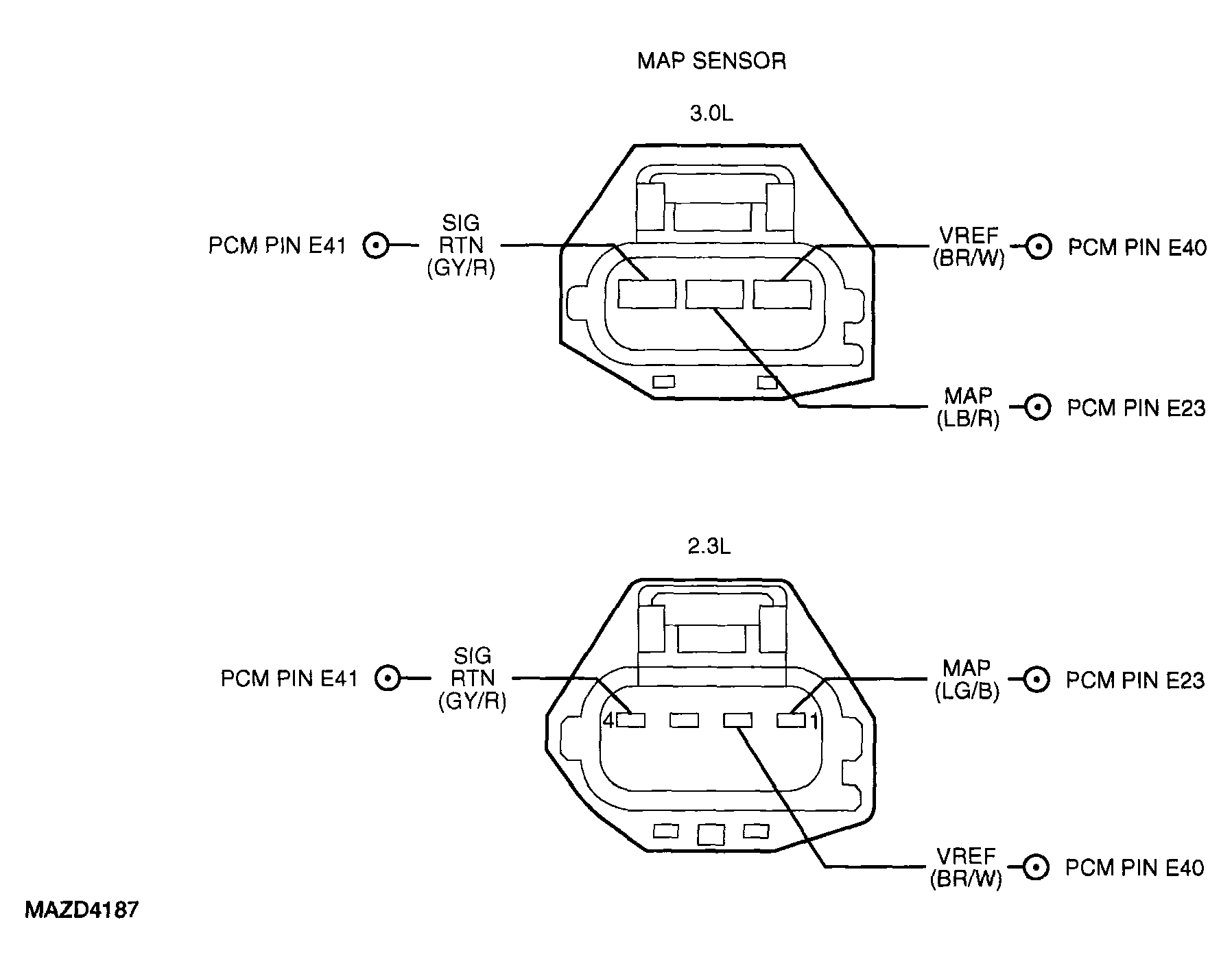 Courtesy of MAZDA MOTORS CORP.
|
DTC P0105, P0106, P0107, P0108, P0109 DIAGNOSTIC PROCEDURE
| STEP |
INSPECTION |
ACTION |
| 1 |
- Was PCM Quick Test performed?
|
Yes |
Go to next step. |
| No |
Perform PCM Quick Test. See
PCM QUICK TEST
. |
| 2 |
CHECK VOLTAGE BETWEEN VREF AND SIGRTN AT MAP SENSOR
- Disconnect MAP sensor.
- Key ON, Engine OFF (KOEO).
- Measure the voltage between MAP sensor connector pin 1 and pin 3 (3.0L), or pin 2 and pin 4 (2.3L).
- Is the voltage between 4.0-5.5 volts?
|
Yes |
Key OFF.
Go to next step. |
| No |
Key OFF.
GO to
TEST 1: VEHICLE REFERENCE VOLTAGE (VREF)
. |
| 3 |
CHECK MAP SENSOR OPERATION
- Key OFF.
- Install a jumper wire between MAP sensor pin 1, harness side and MAP sensor pin 1, component side.
- Install a jumper wire between MAP sensor pin 3, harness side and MAP sensor pin 3, component side.
- Key ON, Engine Running (KOER).
- Measure the voltage between MAP sensor connector pin 2, sensor side and ground.
- Briefly increase engine RPM to 3, 000 RPM, then return to idle.
- Monitor MAP voltage.
- Did the voltage reading rapidly increase to greater than 2 volts, then rapidly decrease to less than 1 volt?
|
Yes |
Key OFF.
Go to next step. |
| No |
Key OFF.
Replace the MAP sensor.
Go to step 6. |
| 4 |
CHECK MAP CIRCUIT FOR SHORT TO VREF AND SIGRTN IN HARNESS
- Disconnect PCM.
- Measure the resistance between MAP sensor pin 1 and pin 2, harness side.
- Measure the resistance between MAP sensor pin 2 and pin 3 (3.0L), harness side, or between MAP sensor pin 1 and pin 4 (2.3L), harness side.
- Are the resistances greater than 10K ohms?
|
Yes |
Go to next step. |
| No |
Repair short between circuits.
Go to step 6. |
| 5 |
CHECK MAP CIRCUIT FOR OPEN IN HARNESS
- Install Breakout Box, leave PCM disconnected.
- Measure the resistance between PCM test pin E23 and MAP sensor pin 1 (2.3L) or pin 2 (3.0L), harness side.
- Is the resistance less than 5 ohms?
|
Yes |
Replace PCM.
See
POWERTRAIN CONTROL MODULE (PCM)
.
Go to next step. |
| No |
Repair open circuit.
Go to next step. |
| 6 |
VERIFY TROUBLESHOOTING OF DTCs COMPLETED
|
Yes |
Go to applicable DTC inspection. |
| No |
Troubleshooting complete. |