Installation Note
- Clean and inspect the reverse servo piston bore and the reverse band servo piston and rod.
- Install the reverse band servo piston and rod into the servo bore along with a reverse servo return spring.
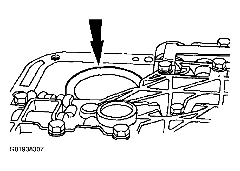 Courtesy of MAZDA MOTORS CORP.
- Install SST
:
- Install a new reverse servo separator plate cover gasket.
- Tighten the three screws.
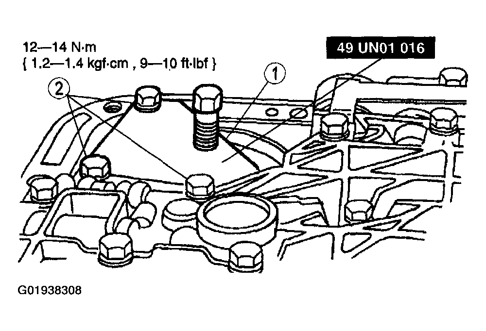 Courtesy of MAZDA MOTORS CORP.
- Tighten the servo gauge adjusting screw.
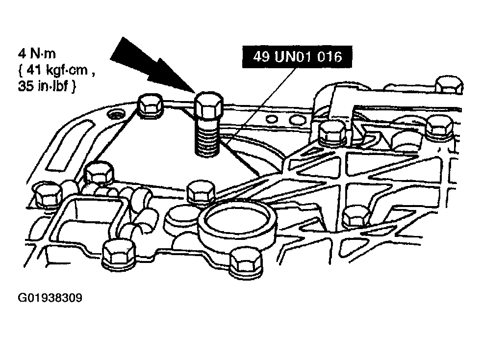 Courtesy of MAZDA MOTORS CORP.
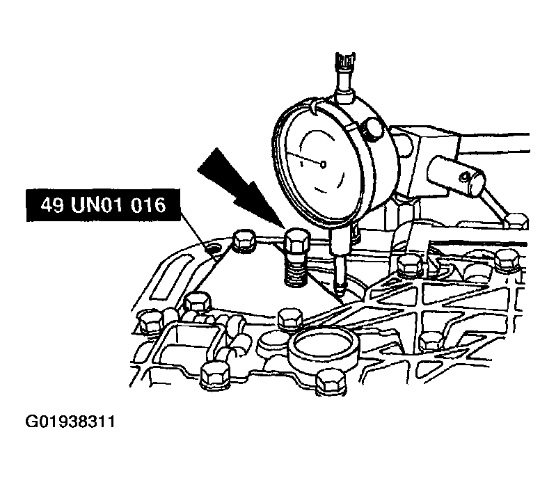
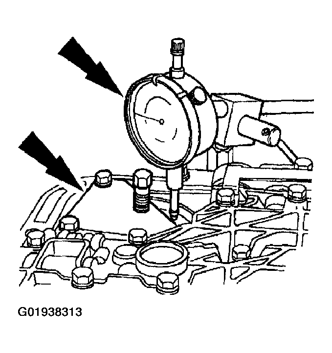
- Install dial indicator with bracketry on the transmission case.
- Position the indicator on the piston pad.
- Set the dial indicator to zero.
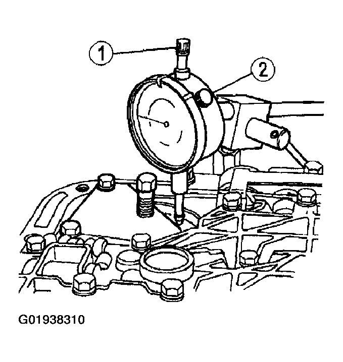 Courtesy of MAZDA MOTORS CORP.
NOTE:
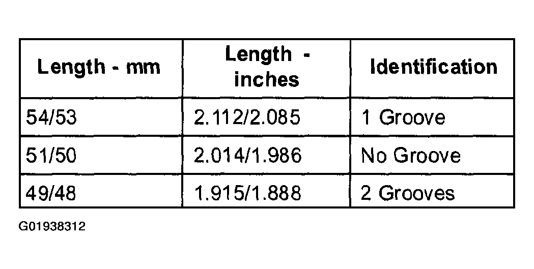
- If the piston travel in this step is 3-5.6 mm (0.120-0.220 in), it is within specification. If the piston travel is greater than 5.6 mm (0.220 in), use the next longer piston and rod. If the piston travel is less than 3 mm (0.120 in), use the next shorter piston and rod.
- Back out the servo gauge adjusting screw until it bottoms out on the tool. Record the distance the servo piston traveled.
 Courtesy of MAZDA MOTORS CORP.
CAUTION:
- Make sure the test spring is removed after this step.
- Use the above procedure to check the piston travel with the newly selected reverse band servo piston and rod (if required) to make sure that the piston travel is 3-5.6 mm (0.120-0.220 in). Remove the servo gauge and the reverse band servo return spring.
- Grooves are located on reverse servo rod.
 Courtesy of MAZDA MOTORS CORP.
 Courtesy of MAZDA MOTORS CORP.
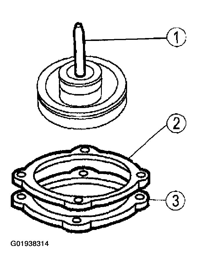
- Install the selected reverse band servo piston and rod.
- Install the reverse band servo piston and rod assembly.
- Install a new reverse servo separator plate cover gasket.
- Install the reverse band servo cover.
- Loosely install the reverse servo piston cover bolts.
 Courtesy of MAZDA MOTORS CORP.
- Tighten the servo cover bolts in the sequence shown.
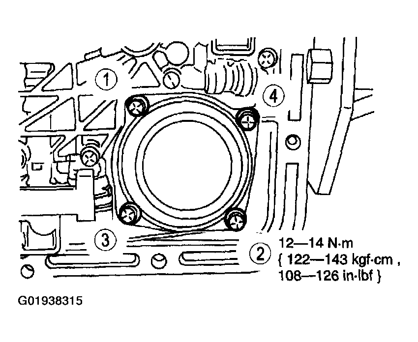 Courtesy of MAZDA MOTORS CORP.
- Install the (1) oil strainer.
- Install the (2) bolt.
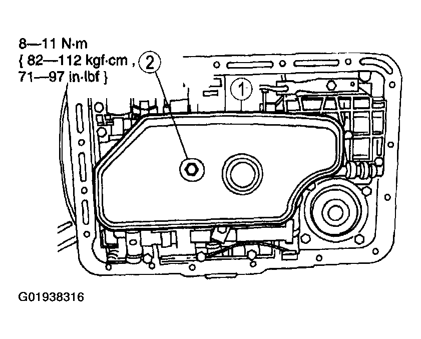 Courtesy of MAZDA MOTORS CORP.
- Position a new oil pan gasket on the transmission fluid pan.
- Install and align the oil pan.
- Loosely install the 18 oil pan bolts.
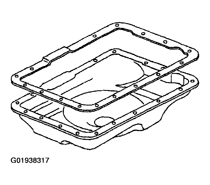 Courtesy of MAZDA MOTORS CORP.
- Tighten the oil pan bolts.
- Use a crisscross sequence to tighten the oil pan bolts.
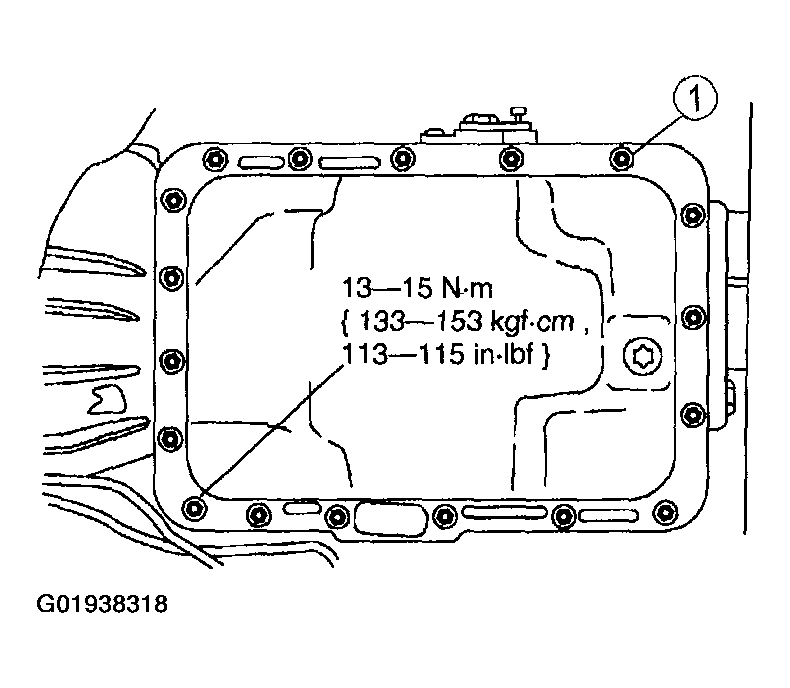 Courtesy of MAZDA MOTORS CORP.
- Lower the vehicle.
NOTE:
- When the battery has been disconnected and reconnected, some abnormal drive symptoms can occur while the vehicle relearns its adaptive strategy. The customer needs to be notified that they may experience slightly different upshifts either soft or firm and this is a temporary condition and will eventually return to normal operating condition.
- Connect the negative battery cable.
- Fill the transmission to the proper fluid level and check for proper transmission operation.