Installation Note
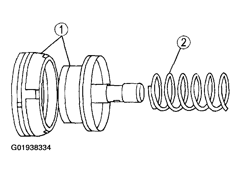
- Assemble the intermediate band servo cover, intermediate band servo piston, and the servo piston spring.
- Install the intermediate band servo piston into the intermediate band servo cover.
- Install the servo piston spring on the intermediate band servo piston.
 Courtesy of MAZDA MOTORS CORP.
CAUTION:
- Do not damage O-ring during installation. Do not press servo cover and O-ring past relief hole in case, or O-ring damage may occur.
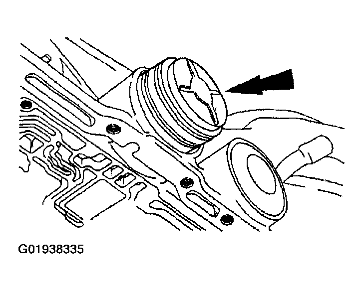
- Install the intermediate band servo piston assembly into the transmission case.
- Lubricate intermediate band servo cover O-ring with petroleum jelly.
 Courtesy of MAZDA MOTORS CORP.
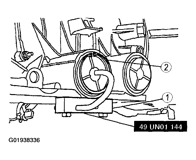
- Using SST
, install the intermediate band servo cover retaining ring.
- Install the SST
and compress the intermediate band servo cover.
- Install the intermediate servo cover retaining ring.
 Courtesy of MAZDA MOTORS CORP.
- Install the catalytic converter; see THREE-WAY CATALYTIC CONVERTER REMOVAL/INSTALLATION - 2.3L
for 2.3L engine or THREE-WAY CATALYTIC CONVERTER REMOVAL/INSTALLATION - 3.0L
for 3.0L engine or THREE-WAY CATALYTIC CONVERTER REMOVAL/INSTALLATION - 4.0L
for 4.0L engine.
- Install the digital transmission range (TR) sensor; see DIGITAL TRANSMISSION RANGE SENSOR REMOVAL/INSTALLATION
.
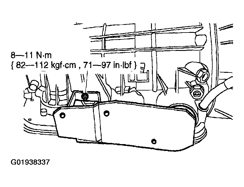
- Position the transmission modulator heat shield on the transmission and install the nut (5R44E/5R55E only).
 Courtesy of MAZDA MOTORS CORP.
- Install the shift cable.
- Install the shift cable.
- Install the shift cable to the manual control lever.
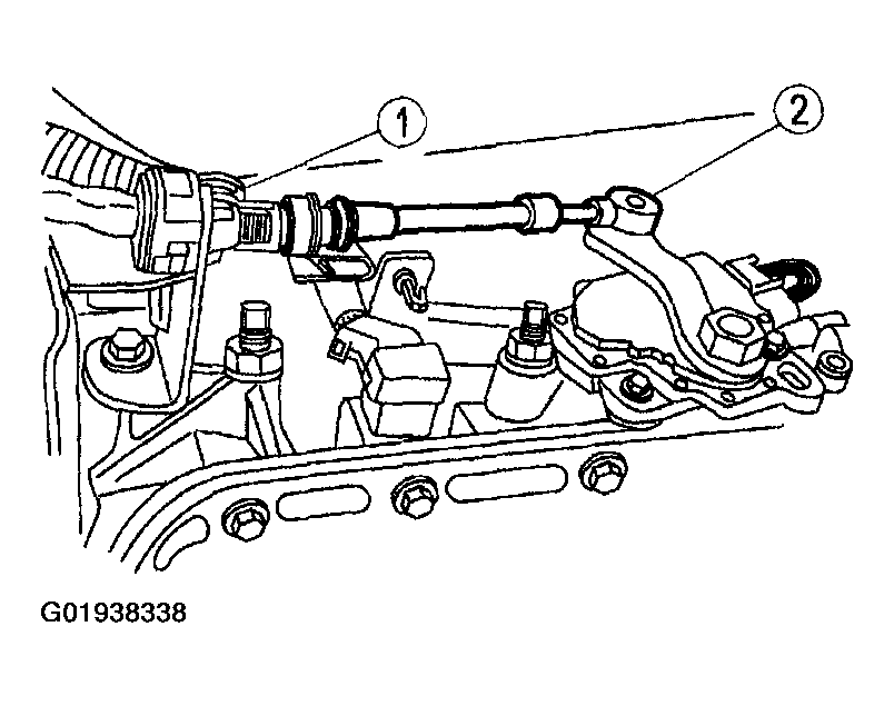 Courtesy of MAZDA MOTORS CORP.
- Install the control valve body; see CONTROL VALVE BODY REMOVAL/INSTALLATION
.
- Adjust the intermediate band; see BAND ADJUSTMENTS
.
- Lower the vehicle.
NOTE:
- When the battery has been disconnected and reconnected, some abnormal drive symptoms can occur while the vehicle re-learns its adaptive strategy. The customer needs to be notified that they may experience slightly different upshifts either soft or firm and this is a temporary condition and will eventually return to normal operating condition.
- Connect the negative battery cable.