Diagnostic Procedures
- Record freeze frame data. Check for service bulletins and on-line information. Repair as necessary. After repair, go to next step.
- Verify Current Input Signal Status - Is Concern Intermittent Or Constant -
Disconnect PCM 104-pin harness connector. Connect 104-pin Breakout Box (49-UN01-130) between PCM and PCM harness connector. See Figure. Start engine. Measure voltage at breakout box terminal No. 34. If voltage reading is less than .2 volt, go to next step. If voltage reading is not as specified, problem is intermittent. See INTERMITTENTS
in TROUBLE SHOOTING - NO CODES article.
- Verify BARO V PID When EGR Boost Sensor Connector Is Disconnected -
Disconnect EGR boost sensor 3-pin harness connector. Access BARO V PID. If PID reading is more than 4.8 volts, go to next step. If PID is not as specified, go to step 5.
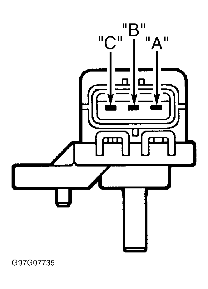
- Check Power Supply Circuit Voltage At EGR Boost Sensor Connector -
If DTCs P0122 and P0107 are also present, trouble shoot reference voltage malfunction. See REFERENCE VOLTAGE . Turn ignition on, engine off. Measure voltage in Pink/Blue wire between ground and EGR boost sensor 3-pin harness connector terminal "C". See Fig 1. See appropriate wiring diagram under ENGINE PERFORMANCE in WIRING DIAGRAMS. If 4.5-5.5 volts is present, check for poor connection at EGR boost sensor terminal "C". If problem is present, repair as necessary. If connection is okay, replace EGR boost sensor. After repair, go to step 7. If 4.5-5.5 volts is not present, repair open in Pink/Blue wire between PCM 104-pin harness connector terminal No. 90 and EGR boost sensor 3-pin harness connector terminal "C". See Figure. After repair, go to step 7.
- Inspect EGR Boost Sensor Signal Circuit For Short To Ground -
Turn ignition off. Disconnect PCM 104-pin harness connector. Check continuity between ground and EGR boost sensor 3-pin harness connector terminal "B" (Violet/Red wire). If continuity is not present, go to next step. If continuity is present, repair short in Violet/Red wire between EGR boost sensor 3-pin harness connector terminal "B" and PCM 104-pin harness connector terminal No. 34. After repair, go to step 7.
- Inspect EGR Boost Sensor Signal And Ground Circuit For Short To Each Other -
Check continuity between EGR boost sensor 3-pin harness connector terminal "A" (Brown/Yellow wire) and terminal "B" (Violet/Red wire). If continuity is not present, go to next step. If continuity is present, repair short between circuits. After repair, go to next step.
- Verify Trouble Shooting Of DTC P0107 Completed -
Reconnect all components. Turn ignition on, engine off. Using scan tool, clear DTC. See CLEARING DIAGNOSTIC TROUBLE CODES under SELF-DIAGNOSTIC SYSTEM. Start engine. Access IAT PID. Ensure IAT PID is more than 50°F (10°C). Recheck DTCs. If DTC P0107 is present, replace PCM. After repair, go to next step. If DTC P0107 is not present, go to next step.
- Verify After Repair Procedure -
Using scan tool, perform After Repair Procedure. See AFTER REPAIR PROCEDURE . If no other DTCs are present, testing is complete. If any other DTC is present, go to applicable test and repair.
 Courtesy of MAZDA MOTORS CORP.