Component Tests: Actuator
NOTE:
Actuator and control module are an integral unit.
- Locate actuator in left rear corner of engine compartment. Leave actuator harness connector attached unless otherwise specified. Using a DVOM, backprobe specified terminals of actuator harness connector while performing appropriate test condition. See ACTUATOR TEST
table. See Fig 1
.
- If voltage measurements or continuity measurements are not as specified, check components and wiring. See WIRING DIAGRAMS
. If components and wiring are okay, but system is still not functioning properly, replace actuator.
ACTUATOR TEST
| Terminal (Signal)/Test Condition |
Value |
| A (Vehicle Speed Sensor) |
| At All Times |
Continuity To Ground |
| B (Brake Switch) |
| Brake Pedal Released |
Battery Voltage |
| Brake Pedal Depressed |
0 Volts |
| D (Power Supply) |
| Ignition On |
Battery Voltage |
| Ignition LOCK Or ACC |
0 Volts |
| E (Cruise Control Switch) |
| SET/COAST Switch Depressed |
240 Ohms |
| RESUME/ACCEL Switch Depressed |
910 Ohms |
| Other |
No Continuity To Ground |
| F (Cruise Control Switch) |
| SET/COAST Switch Depressed |
240 Ohms |
| RESUME/ACCEL Switch Depressed |
910 Ohms |
| Other |
No Continuity To Ground |
| G (Brake Switch) |
| Brake Pedal Depressed |
Battery Voltage |
| Brake Pedal Released |
0 Volts |
| H (Vehicle Speed Sensor) |
| Vehicle Speed 12 MPH |
About 4.5 Volts |
| Vehicle Speed 31 MPH |
About 8.5 Volts |
| Vehicle Speed 56 MPH |
About 16.5 Volts |
| I (Clutch Switch - M/T) |
| Clutch Pedal Depressed |
Continuity To Ground |
| Clutch Pedal Released |
No Continuity To Ground |
| I (Inhibitor Switch - A/T) |
| Gear Selector In Park Or Neutral |
Continuity To Ground |
| Gear Selector Not In Park Or Neutral |
No Continuity To Ground |
| J (Indicator Light Output) |
| Ignition On |
Battery Voltage |
| Ignition Lock Or ACC |
0 Volts |
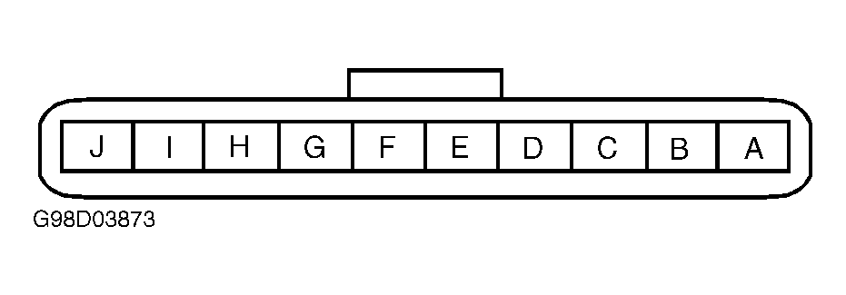 Courtesy of MAZDA MOTORS CORP.