Clutch Pedal Position (CPP) Switch Malfunction
DTC P0704, P1709 DETECTION CONDITION AND POSSIBLE CAUSE
| DTC P0704, P1709 |
CLUTCH PEDAL POSITION (CPP) SWITCH MALFUNCTION |
| DETECTION CONDITION |
- P0704 indicates a malfunction of the CPP switch has been detected.
- P1709 indicates the voltage is high or the switch is open when the voltage should be low or the switch should be closed grounding the circuit.
|
| POSSIBLE CAUSE |
- Starter relay disconnected during Quick Test.
- PNP/CPP circuit shorted to power.
- PNP/CCP open in SIG RTN circuit.
- Damaged PNP or CPP switch.
- Damaged PCM.
|
| HINT |
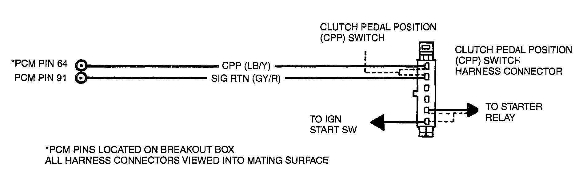
CPP Switch Description
- Input to the PCM indicating the clutch pedal position (engaged or disengaged).
- The PCM provides a 5-volt reference (VREF) signal to the CPP switch.
- If the switch is closed indicating the clutch pedal is engaged, the output voltage from the PCM is grounded through the signal return line to the PCM, and there is 1 volt or less indicating there is a reduced load on the engine.
- If the CPP switch is open, meaning the clutch pedal is disengaged, the input on the CPP signal to the PCM will be approximately 5 volts indicating a load on the engine.
|
 Courtesy of MAZDA MOTORS CORP. Courtesy of MAZDA MOTORS CORP.
|
DTC P0704, P1709 INSPECTION
| STEP |
INSPECTION |
ACTION |
| 1 |
- Was PCM Quick Test performed?
|
Yes |
Go to next step. |
| No |
Perform PCM Quick Test. |
| 2 |
CHECK CPP/PNP SWITCH FUNCTION
NOTE:
During KOEO Self Test, clutch pedal must be down for M/T or the gear shift lever must be in NEUTRAL for A/T.
- Key ON, Engine OFF (KOEO).
- Access CPP/PNP PID and observe PID cycling ON/OFF with clutch pedal up, then down (M/T) or gear shift lever in gear, then NEUTRAL (A/T).
- Does the reading change from ON to OFF?
|
Yes |
Fault intermittent.
Disconnect PCM.
Inspect both ends of the connector for damaged or pushed out pins, corrosion, loose wires.
Repair as necessary.
If OK, replace PCM. See COMPUTERIZED ENGINE CONTROLS
.
Go to step 6. |
| No |
Go to next step. |
| 3 |
CHECK CPP SWITCH
- Key OFF.
- Locate the CPP switch near the clutch pedal.
- Inspect switch and bracket for damage, bent or broken conditions. Repair as required.
- Disconnect CPP harness connector and inspect for damage, pushed out or broken pins and broken wires. Repair as necessary.
- Measure resistance across the CPP switch terminals with the clutch pedal down.
- Is the resistance less than 5.0 ohms?
|
Yes |
Go to next step. |
| No |
Replace the CPP switch. See ELECTRICAL COMPONENT LOCATOR
.
Go to step 6. |
| 4 |
CHECK RESISTANCE OF CPP CIRCUIT
- Disconnect NGS Tester.
- Disconnect PCM.
- Install Breakout Box, leave PCM disconnected.
- Measure resistance of CPP circuit between PCM test pin 64 and the CPP switch harness connector.
- Measure resistance of CPP circuit between PCM test pin 64 and the CPP switch harness connector.
- Is each resistance less than 5.0 ohms?
|
Yes |
Go to next step. |
| No |
Repair open circuit.
Go to step 6. |
| 5 |
CHECK CPP CIRCUIT FOR SHORT
- Measure resistance between PCM test pin 64 (CPP) and PCM test pin 91 (SIG RTN).
- Measure resistance between PCM test pins 64 (CPP) and chassis ground.
- Is each resistances greater than 10K ohms?
|
Yes |
Replace PCM. See COMPUTERIZED ENGINE CONTROLS
.
Go to step 6. |
| No |
Repair short circuit.
Go to step 6. |
| 6 |
VERIFY TROUBLESHOOTING OF DTCs COMPLETED
- Make sure to reconnect all disconnected connectors.
- Clear DTCs from PCM memory using NGS tester generic OBD-II function.
- Perform PCM Quick Test.
- Is same DTC present?
|
Yes |
Replace PCM. See COMPUTERIZED ENGINE CONTROLS
.
Repeat PCM Quick Test. |
| No |
If any other DTC is present, go to applicable DTC inspection.
If no DTC is present, troubleshooting complete. |