Test No. 1
- Check ROOM fuse. If fuse is faulty, replace ROOM fuse (repair circuit if shorted). If fuse is okay, remove key from ignition switch. Remove CPU from joint box. Measure voltage at terminal 3B of joint box connector. See Fig 1.
- If battery voltage is not present, repair wiring between ROOM fuse and CPU. If battery voltage is present, check continuity between ground and terminal 3D of joint box connector. If continuity does not exist, repair wiring between CPU and ground.
- If continuity exists, measure voltage at terminal 3N of joint box connector. If battery voltage is present, replace key reminder switch or repair wiring between ROOM fuse and CPU.
- If battery voltage is not present, open both front doors. Check continuity between ground and terminal 3M of joint box connector. If continuity does not exist, go to next step. If continuity exists, check continuity between ground and terminal 3H of joint box connector. If continuity does not exist, go to step 6). If continuity exists, go to step 7).
- Remove driver door switch. Check continuity between door switch terminal and switch body with switch button released. If continuity exists, repair wiring between CPU and door switch. If continuity does not exist, replace door switch.
- Remove front passenger door switch. Check continuity between door switch terminal and switch body with switch button released. If continuity exists, repair wiring between CPU and door switch. If continuity does not exist, replace door switch.
- Install CPU to joint box. Disconnect CPU 20-pin connector. See Fig 1. Open rear door. Check continuity between ground and terminal 2D (Red wire) of CPU 20-pin connector. If continuity exists, reconnect CPU 20-pin connector and go to step 9). If continuity does not exist, go to next step.
- Remove door switch from either rear door. Check continuity between door switch terminal and switch body with switch button released. If continuity exists, repair wiring between CPU and door switch. If continuity does not exist, replace door switch. Perform same procedure at other rear door switch.
- Disconnect CPU 16-pin connector. Close trunk and hood. Check continuity between ground and terminal 1D (Green/Red wire) of CPU 16-pin connector. If continuity exists, go to next step. If continuity does not exist, check continuity between ground and terminal 1F (Blue/Red wire) of CPU 16-pin connector. If continuity exists, go to step 11). If continuity does not exist, reconnect CPU 16-pin connector and go to step 12).
- Remove trunk switch from trunk latch assembly. Check continuity between trunk switch connector terminals. With switch lever pushed (trunk closed), continuity should not exist. With switch lever released (trunk open), continuity should exist. If continuity is not as specified, replace trunk switch. If continuity is as specified, repair wiring between CPU and trunk switch.
- Remove hood switch from hood latch assembly. Check continuity between hood switch connector terminals. With switch lever pushed (hood closed), continuity should not exist. With switch lever released (hood open), continuity should exist. If continuity is not as specified, replace hood switch. If continuity is as specified, repair wiring between CPU and hood switch.
- Disconnect CPU 20-pin connector. See Fig 1. Ground terminal 2M (Red/Green wire) of CPU 20-pin connector. If security light illuminates, replace CPU. If security light does not illuminate, remove instrument cluster. Measure voltage at terminal 1I (Blue/Red wire) of instrument cluster connector No. 1 (White, 14-pin connector). See Fig 2.
- If battery voltage is not present, repair wiring between ROOM fuse and instrument cluster. If battery voltage is present, measure voltage at terminal 1H (Red/Green wire) of instrument cluster connector No. 1. If battery voltage is present, repair wiring between instrument cluster and CPU. If battery voltage is not present, replace security light.
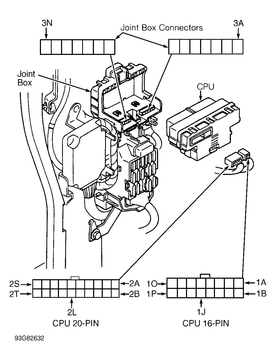 Courtesy of MAZDA MOTORS CORP.
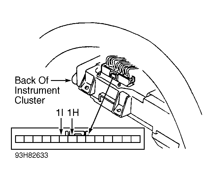 Courtesy of MAZDA MOTORS CORP.