IGNITOR Check
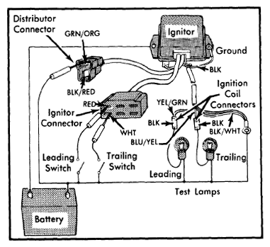
- Disconnect connectors from pick-up coil lead and from ignition coils. See Fig 1. Disconnect 2-pin connector from between switches and ignitor.
 Courtesy of NOT AVAILABLE
- Make a circuit as shown in Fig 1. Use two 12 volt lamps with less than 10 watt rating. Operate switch "ON" and "OFF" to be sure test lamps work. Apply battery power to green/orange wire in 2-pin connector. Operate trailing side switch "ON" and "OFF". Trailing side lamp should not flash.
- Now apply battery power to black/red wire in same connector. Operate trailing side switch "ON" and "OFF". Test lamp of leading lamp should flash. If test results differ, replace ignitors.
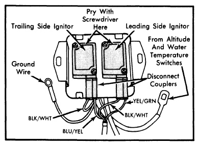
- To replace ignitors, disconnect couplers from ignitor leads and remove ignitor assembly. See Fig 2. Grip coupler (not wires) and remove from each ignitor. Loosen ignitor attaching screws. Insert thin screwdriver between ignitor and aluminum base plate (on end of ignitor opposite coupler connections), and pry upward on ignitor a little at a time. Remove from plate. Clean ignitor and plate mounting surfaces and install new ignitor. Tighten attaching screws to 10-17 INCH lbs. (12-20 cmkg). Reinstall ignitor assembly on front of shock absorber housing and connect couplers to ignitor leads.
 Courtesy of NOT AVAILABLE