Relief Solenoid Valve Signal Check
- Warm engine to normal operating temperature. Connect tachometer to engine. With voltmeter connected to good ground, insert other probe into light green wire terminal of relief solenoid valve connector (do not detach connector). On all models with Auto. Trans. and Calif. models with Man. Trans., disconnect vacuum switch electrical coupler.
- On all models, start engine and increase engine speed to 2000 RPM, using throttle. Slowly decrease engine speed and record speed at which current begins flowing to terminal. It should be 1050-1250 RPM. Stop engine.
- Slowly increase engine speed from idle and check speed at which current stops flowing to solenoid. Difference between this speed and speed noted in previous step (1050-1250), should be 80-220 RPM.
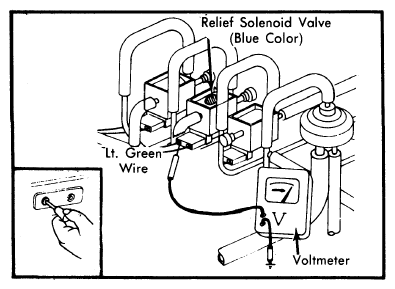 Courtesy of MAZDA MOTORS CORP.
- On all models with Auto. Trans. and Calif. models with Man. Trans., continue with following tests:
- Start engine with choke knob pulled fully out. Note voltmeter to ensure current is reaching solenoid terminal. Push choke knob back into position. Place jumper wire on vacuum switch connector as shown. See Fig 2.
- Increase engine speed to 4600 RPM, using throttle. Note that current should stop flowing to terminal within 1 3/4-2 1/2 minutes from pulling choke knob in step 5).
- Next, return engine to idle and slowly increase engine speed, noting that current stops flowing to terminal when engine speed exceeds 2700-3300 RPM (3000-3600 RPM on Calif. Auto. Trans. models).
- If relief solenoid valve does not perform as described, replace solenoid valve. On all models with Auto. Trans. and Calif. models with Man. Trans., check timer and components before replacing solenoid valve.
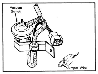 Courtesy of MAZDA MOTORS CORP.