Pinpoint Test G: DTC U3003:16
- G1 RECHECK THE BCM DTCs
- Ignition ON.
- Enter the following diagnostic mode on the scan tool: BCM Self-Test.
- Using a scan tool, clear the DTCs. Repeat the BCM self-test.
- Is DTC U3003:16 still present?
- Yes
: GO to G2.
- No
: The system is operating normally at this time. The DTC may have been set due to a previous low battery voltage condition.
- G2 CHECK FOR CHARGING SYSTEM DTCs IN THE PCM
- Enter the following diagnostic mode on the scan tool: PCM Self-Test.
- Using a scan tool, perform the PCM KOEO self-test.
- Retrieve the continuous memory DTCs from the PCM.
- Is DTC P0562, P0620, P0622, P0625, P0626 or P065B set in the PCM?
- G3 CHECK THE BATTERY CONDITION AND STATE OF CHARGE
- Ignition OFF.
- Check the battery condition and verify the battery is fully charged. REFER to
CHARGING SYSTEM
.
- Is the battery OK and fully charged?
- G4 CHECK THE BCM VOLTAGE PID
- Ignition ON.
- Measure and record the voltage at the battery.
- Enter the following diagnostic mode on the scan tool: BCM DataLogger.
- Monitor the BCM voltage PID (V_BATT).
- Is the voltage within 0.2 volt of the recorded battery voltage?
- Yes
: GO to G7.
- No
: GO to G5.
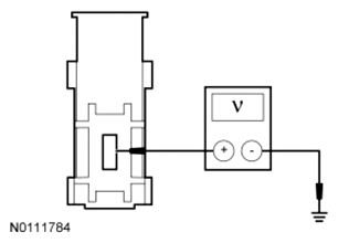
- G5 CHECK THE BCM VOLTAGE SUPPLY
- Ignition OFF.
- Disconnect: BCM C2280G.
- Ignition ON.
- Measure the voltage
between:
| Positive Lead |
Negative Lead |
| Pin |
Circuit |
Pin |
Circuit |
| C2280G-1 |
SBF16 (RD) |
- |
Ground |
 Courtesy of FORD MOTOR CO.
- Is the voltage within 0.2 volt of the recorded battery voltage?
- Yes
: GO to G6.
- No
: REPAIR the circuit for high resistance. CLEAR the DTC.
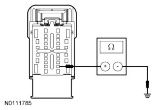
- G6 CHECK THE BCM GROUND CIRCUIT FOR HIGH RESISTANCE
- Ignition OFF.
- Disconnect: BCM C2280D.
- Measure the resistance
between:
| Positive Lead |
Negative Lead |
| Pin |
Circuit |
Pin |
Circuit |
| C2280D-25 |
GD233 (BK) |
- |
Ground |
 Courtesy of FORD MOTOR CO.
- Is the resistance less than 3 ohms?
- Yes
: GO to G7.
- No
: REPAIR the circuit. CLEAR the DTC.
- G7 CHECK FOR CORRECT BCM OPERATION
- Disconnect the BCM connectors.
- Repair:
- corrosion (install new connector or terminals - clean module pins)
- damaged pins - install new terminals/pins
- pushed-out pins - install new pins as necessary
- Reconnect the BCM connectors and make sure they seat and latch correctly.
- Operate the system and determine if the concern is still present.
- Is the concern still present?
- Yes
: CHECK OASIS for any applicable TSBs. If a TSB exists for this concern, discontinue this test and follow TSB instructions. If no TSBs address this concern, INSTALL a new BCM. REFER to BODY CONTROL MODULE (BCM) .
- No
: The system is operating correctly at this time. The concern may have been caused by module connections. ADDRESS the root cause of any connector or pin issues.