Pinpoint Test B: Select Shift Does Not Operate/Overdrive (O/D) Does Not Cancel
- B1 CHECK CIRCUITS CET43 (GY) AND CET42 (GN/VT) INPUT TO THE PCM
- Ignition ON.
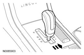
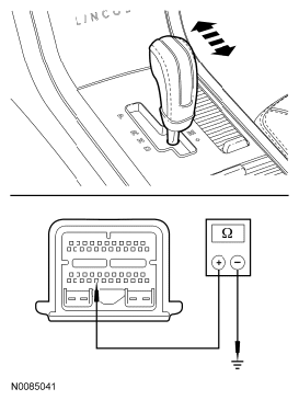
- Move the selector lever to the "M" position.
 Courtesy of FORD MOTOR CO.
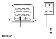
- Disconnect: PCM C175T.
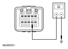
- Measure the resistance between PCM C175T-42, circuit CET43 (GY), harness side and ground.
 Courtesy of FORD MOTOR CO.
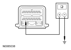
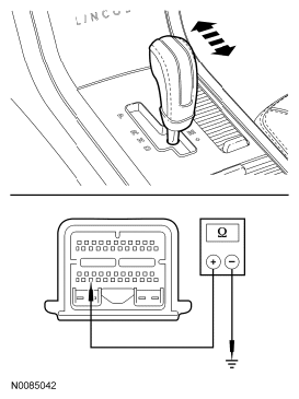
- Measure the resistance between PCM C175T-44, circuit CET42 (GN/VT), harness side and ground.
 Courtesy of FORD MOTOR CO.
- Are the resistances less than 5 ohms?
- Yes:
GO to B4.
- No:
GO to B2
.
- B2 CHECK TRANSMISSION SELECT SHIFT CIRCUITS FOR OPEN
- Disconnect: Selector Lever Harness C3245.
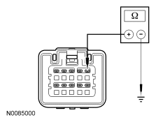
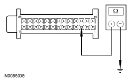
- Measure the resistance between selector lever C3245-5, harness side and ground.
 Courtesy of FORD MOTOR CO.
- Measure the resistance between selector lever C3245-9, harness side and ground.
 Courtesy of FORD MOTOR CO.
- Are the resistances less than 5 ohms?
- Yes:
GO to B3
.
- No:
REPAIR the circuits. TEST system for normal operation.
- B3 CHECK CIRCUITS CET43 (GY) AND CET42 (GN/VT) FOR OPEN
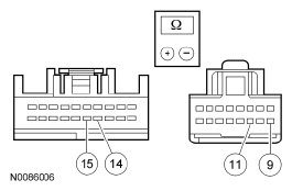
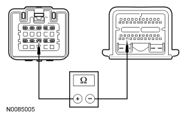
- Measure the resistance between selector lever C3245-7, circuit CET43, harness side and PCM C175T-42.
 Courtesy of FORD MOTOR CO.
- Measure the resistance between selector lever C3245-8, circuit CET43, harness side and PCM C175T-44.
 Courtesy of FORD MOTOR CO.
- Are the resistances less than 5 ohms?
- Yes:
INSTALL a new selector lever. TEST the system for normal operation.
- No:
REPAIR the circuits. TEST the system for normal operation.
- B4 CHECK CIRCUITS CET43 (GY) AND CET42 (GN/VT) FOR SHORT TO GROUND
- Disconnect: Selector Lever Harness C3245.
- Measure the resistance between PCM C175T-42, circuit CET43 (GY), harness side and ground.
Courtesy of FORD MOTOR CO.
- Measure the resistance between PCM C175T-44, circuit CET42 (GN/VT), harness side and ground.
 Courtesy of FORD MOTOR CO.
- Are the resistances greater than 10,000 ohms?
- Yes:
GO to B5
.
- No:
REPAIR circuit. TEST system for normal operation.
- B5 CHECK THE TRANSMISSION SELECTOR LEVER SELECT SHIFT SWITCHES
- Connect: Selector Lever Harness C3245.
- Measure the resistance between PCM C175T-42, circuit CET43 (GY), harness side and ground while moving the selector lever to the " + (ON)" back to "M" (OFF) positions.
 Courtesy of FORD MOTOR CO.
- Measure the resistance between PCM C175T-44, circuit CET42 (GN/VT), harness side and ground while moving the selector lever to the " - (ON)" back to "M" (OFF) positions.
 Courtesy of FORD MOTOR CO.
- Is the resistance less than 5 ohms with the switch ON and greater than 10,000 ohms with the switch OFF?
- Yes:
INSTALL a new PCM.
- No:
INSTALL a new selector lever. TEST the system for normal operation.