Transmission Support Crossmember: Installation
- Position the LH side of the crossmember into the crossmember pocket and loosely install the bolts.
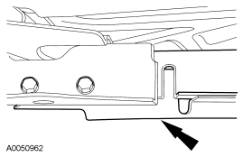 Courtesy of FORD MOTOR CO.
- Position the RH side of the crossmember into the crossmember pocket and loosely install the bolts.
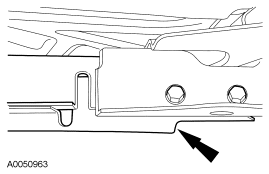 Courtesy of FORD MOTOR CO.
- Tighten the LH crossmember bolts.
- Tighten to 70 Nm (52 lb-ft).
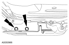 Courtesy of FORD MOTOR CO.
- Tighten the RH crossmember bolts.
- Tighten to 70 Nm (52 lb-ft).
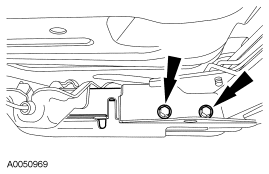 Courtesy of FORD MOTOR CO.
- Install the parking brake cable bracket.
- Tighten to 55 Nm (41 lb-ft).
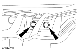 Courtesy of FORD MOTOR CO.
- Lower the transmission onto the crossmember and install the rear transmission insulator nuts.
- Tighten to 30 Nm (22 lb-ft).
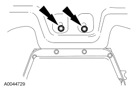 Courtesy of FORD MOTOR CO.
- Remove the transmission jack.
- Install a new gasket and position the RH catalytic converter assembly in place and loosely install the bolts. Do not tighten the bolts at this time.
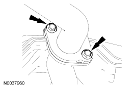 Courtesy of FORD MOTOR CO.
- Install the RH exhaust flange nuts.
- Tighten to 48 Nm (35 lb-ft).
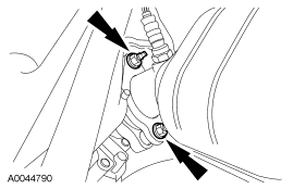 Courtesy of FORD MOTOR CO.
- Tighten the RH exhaust bolts.
- Tighten to 40 Nm (30 lb-ft).
Courtesy of FORD MOTOR CO.
- Connect the RH HO2S sensor connector.
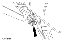 Courtesy of FORD MOTOR CO.
- Connect the RH catalyst monitor connector.
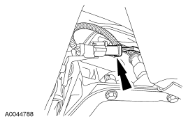 Courtesy of FORD MOTOR CO.
- Install a new gasket and position the LH catalytic converter assembly in place and install the bolts. Do not tighten the bolts at this time.
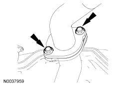 Courtesy of FORD MOTOR CO.
- Install the LH exhaust flange nuts.
- Tighten to 48 Nm (35 lb-ft).
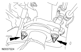 Courtesy of FORD MOTOR CO.
- Tighten the LH exhaust bolts.
- Tighten 40 Nm (30 lb-ft).
Courtesy of FORD MOTOR CO.
- Connect the LH HO2S sensor connector.
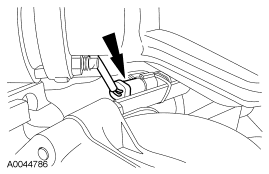 Courtesy of FORD MOTOR CO.
- Connect the LH catalyst monitor connector.
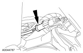 Courtesy of FORD MOTOR CO.