Disassembly And Assembly: Halfshaft: Assembly
- If removed, install a new anti-lock brake sensor indicator ring on the outer CV joint.
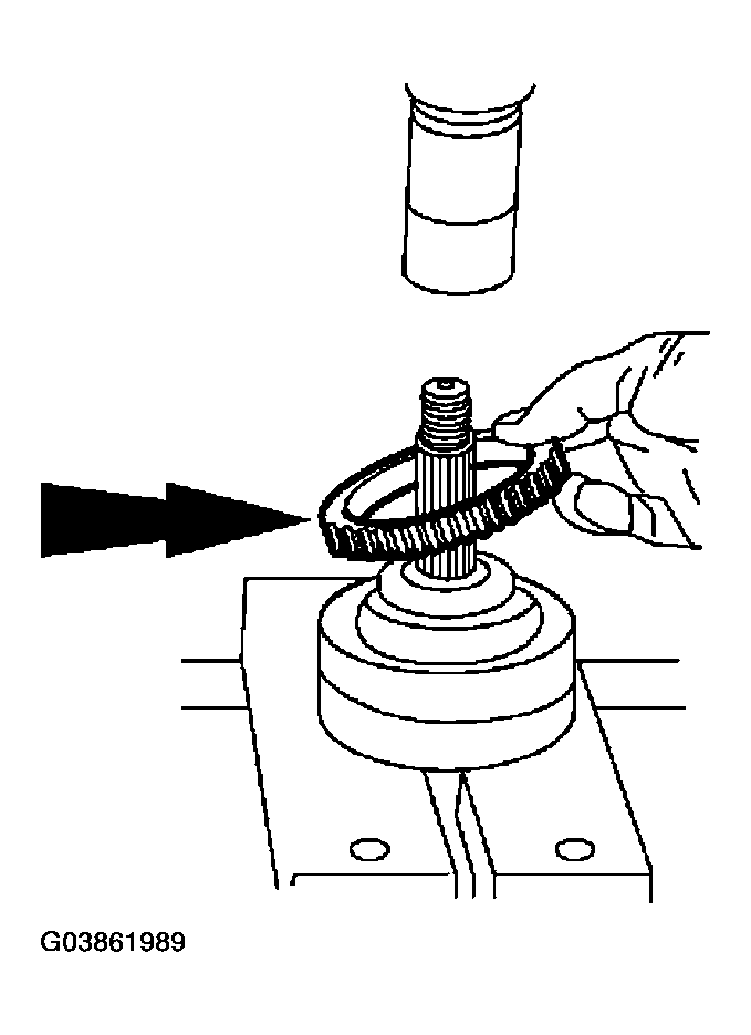 Courtesy of FORD MOTOR CO.
- Lubricate the outboard CV joint.
- Pack the outboard CV joint with 185 grams (6.53 oz) of grease.
- One-third of the grease must be installed in the joint with the remainder placed in the boot.
- Spread the remaining grease evenly inside the boot.
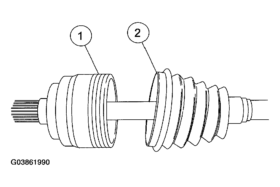 Courtesy of FORD MOTOR CO.
- Position the outboard half shaft boot and the outboard boot clamps.
- Position the boot.
- Position the boot clamps.
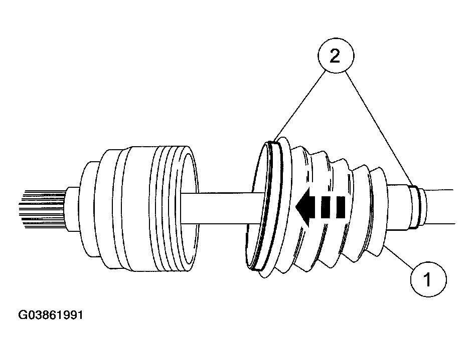 Courtesy of FORD MOTOR CO.
- Install the outboard CV boot clamps.
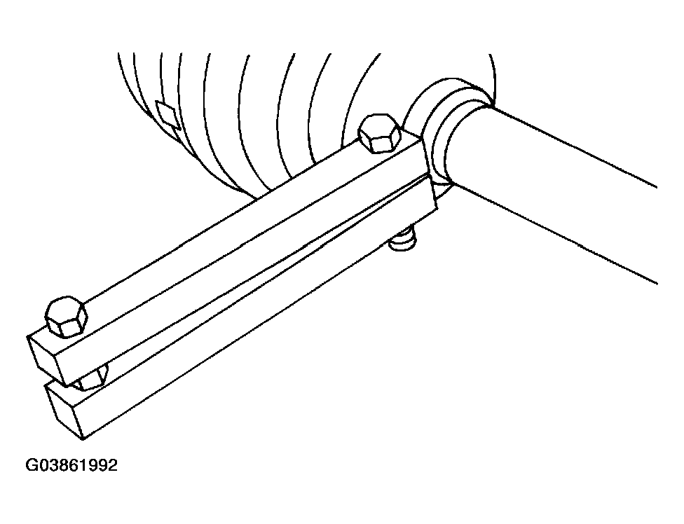 Courtesy of FORD MOTOR CO.
- Position the inboard clamp and boot.
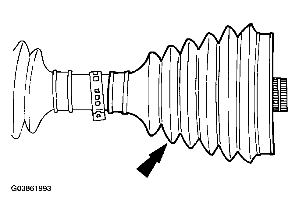 Courtesy of FORD MOTOR CO.
- Install the CV joint and snap ring on the halfshaft.
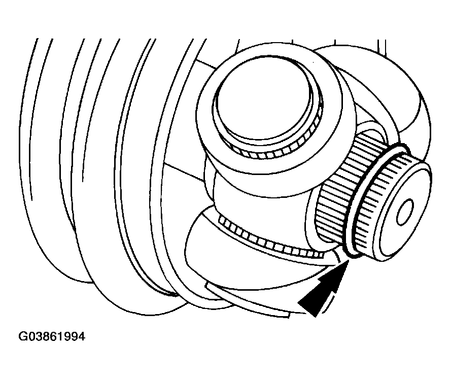 Courtesy of FORD MOTOR CO.
- Install the stop ring.
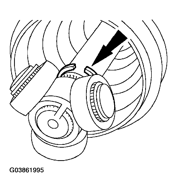 Courtesy of FORD MOTOR CO.
- Fill the inboard CV joint housing with 210 grams (7.41 oz) of grease.
- One-half of the grease must be installed in the joint and the remainder placed in the boot.
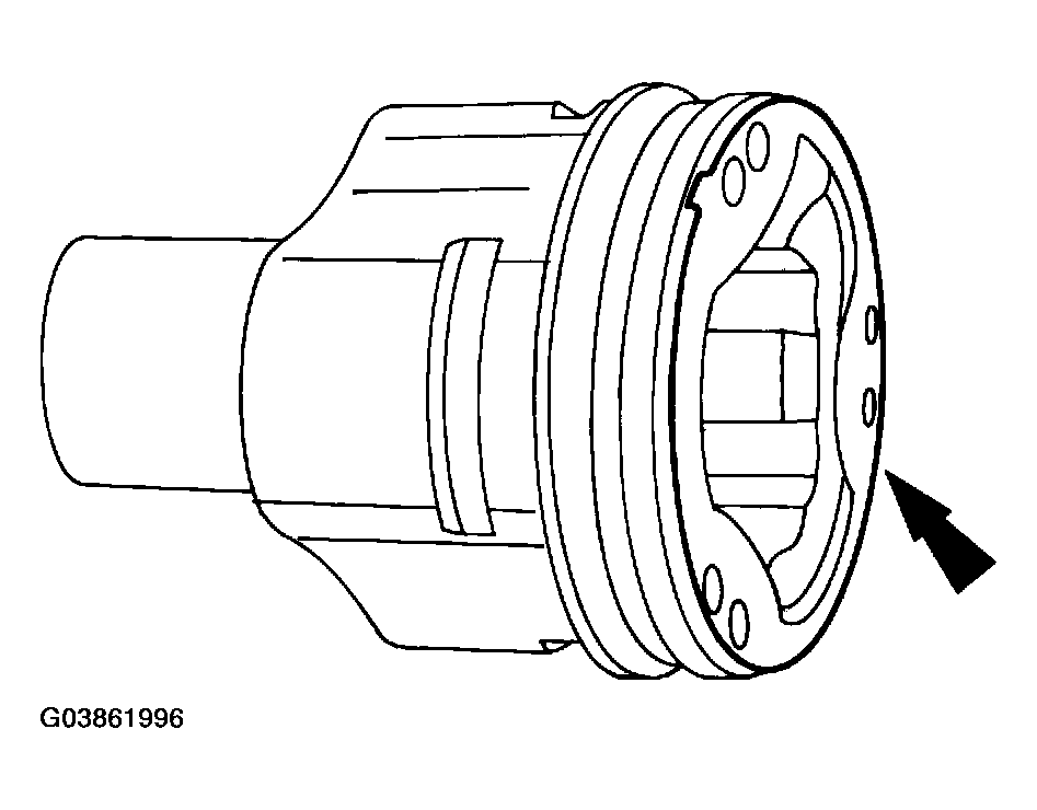 Courtesy of FORD MOTOR CO.
- Position the CV housing on the CV joint.
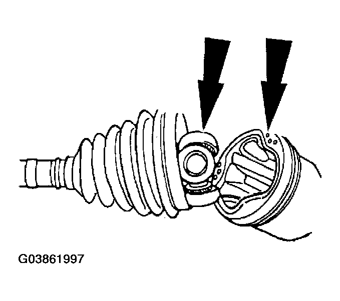 Courtesy of FORD MOTOR CO.
- Position the inboard halfshaft boot and clamp.
- Position the boot in the housing groove.
- Position the boot clamp.
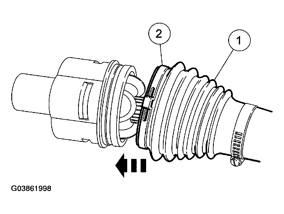 Courtesy of FORD MOTOR CO.
- Set the halfshaft assembled length to specifications. For additional information, refer to SPECIFICATIONS .
- Measure the entire assembly length.
- Push in or pull out on the inner joint as necessary to adjust the halfshaft assembled length.
- Hold the inner joint to prevent the assembled length from changing, and insert a small flat-blade screwdriver between the boot and the joint to equalize the pressure.
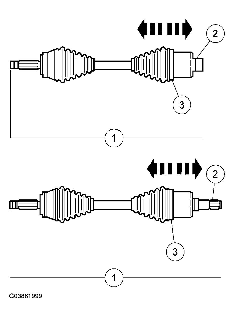 Courtesy of FORD MOTOR CO.
- Using the special tool, install the boot clamps.
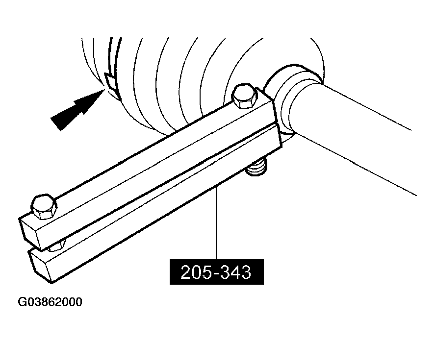 Courtesy of FORD MOTOR CO.
- Install the halfshaft assembly. For additional information, refer to HALFSHAFT .