Intake Manifold: Removal
- Disconnect the fuel spring lock coupling. For additional information, refer to FUEL SYSTEM-GENERAL INFORMATION
.
- Disconnect the battery ground cable. For additional information, refer to BATTERY, MOUNTING AND CABLES
.
- Drain the engine cooling system. For additional information, refer to ENGINE COOLING
.
- Remove the air cleaner outlet pipe - resonator assembly. For additional information, refer to INTAKE AIR DISTRIBUTION & FILTERING
.
- Remove the wiper mounting arm and pivot shaft. For additional information, refer to WIPERS AND WASHERS
.
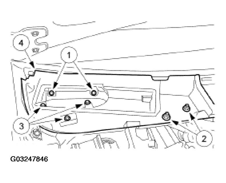
- Remove the RH cowl extension.
- Remove the pin-type retainers.
- Remove the nuts.
- Remove the bolts.
- Remove the extension.
 Courtesy of FORD MOTOR CO.
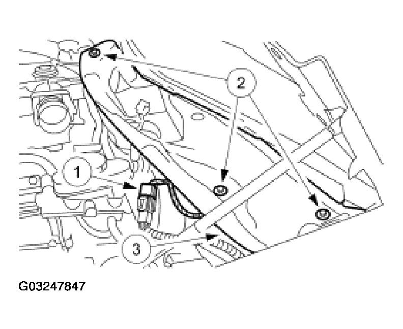
- Remove the LH cowl extension.
- Disconnect the electrical connector.
- Remove the bolts.
- Remove the extension.
 Courtesy of FORD MOTOR CO.
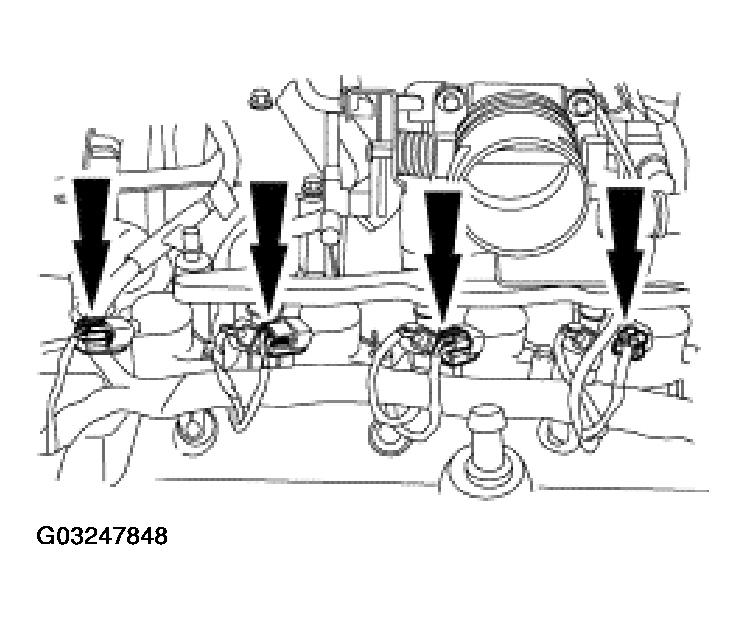
- Disconnect the fuel charging wiring electrical connectors from the eight ignition coils.
 Courtesy of FORD MOTOR CO.
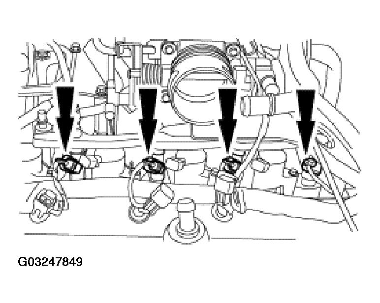
- Disconnect the fuel charging wiring electrical connectors from the eight fuel injectors.
 Courtesy of FORD MOTOR CO.
- Disconnect the accelerator cable, the speed control actuator cable, the throttle return spring and the cable retaining bolts.
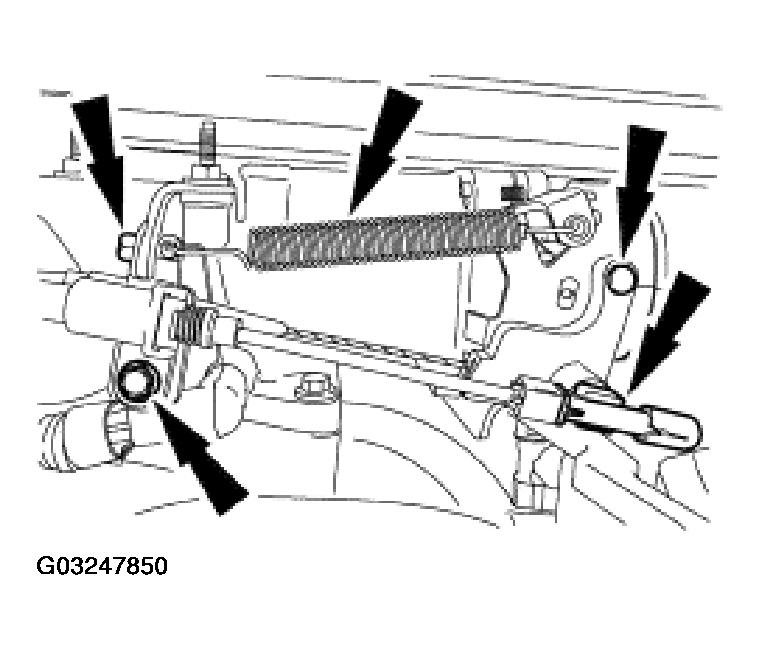 Courtesy of FORD MOTOR CO.
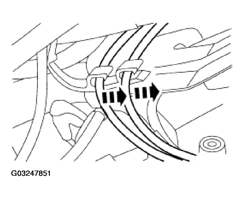
- Remove the cables from the exhaust gas recirculation (EGR) system module tube heat shield and position out of the way.
 Courtesy of FORD MOTOR CO.
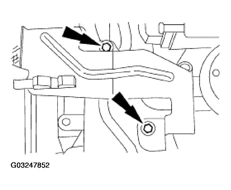
- Remove the bolts and the EGR system module tube heat shield.
 Courtesy of FORD MOTOR CO.
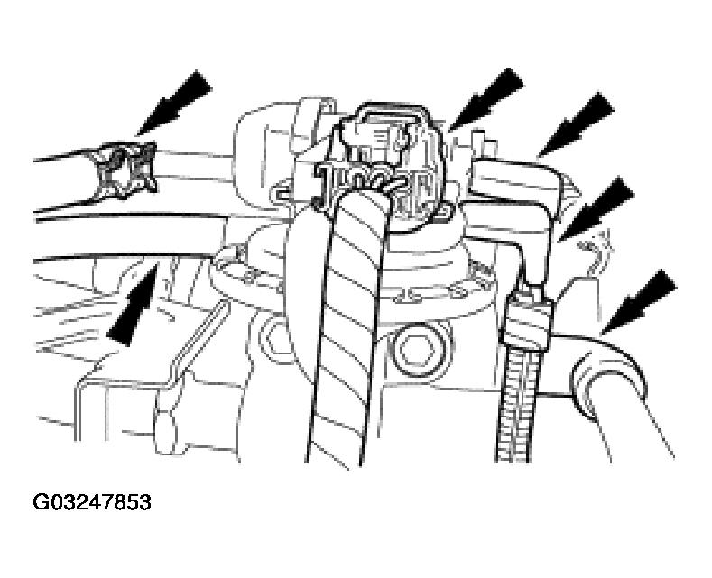
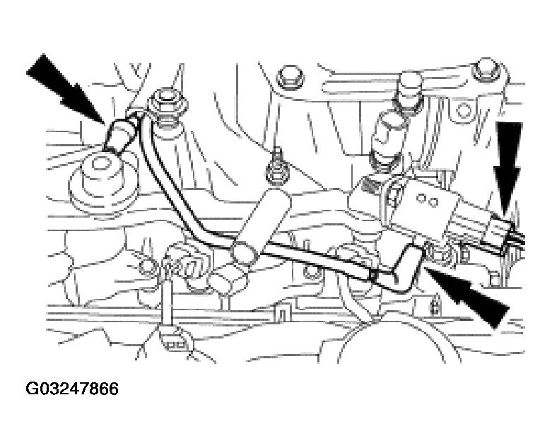
- Disconnect the electrical connector and the vacuum hoses.
 Courtesy of FORD MOTOR CO.
- Disconnect the EVAP canister purge valve vacuum hose.
 Courtesy of FORD MOTOR CO.
- Disconnect the electrical connector and the harness location retainer.
 Courtesy of FORD MOTOR CO.
- Remove the bolts and the generator mounting bracket.
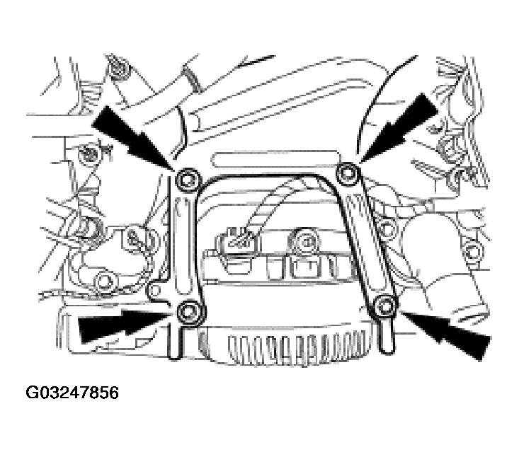 Courtesy of FORD MOTOR CO.
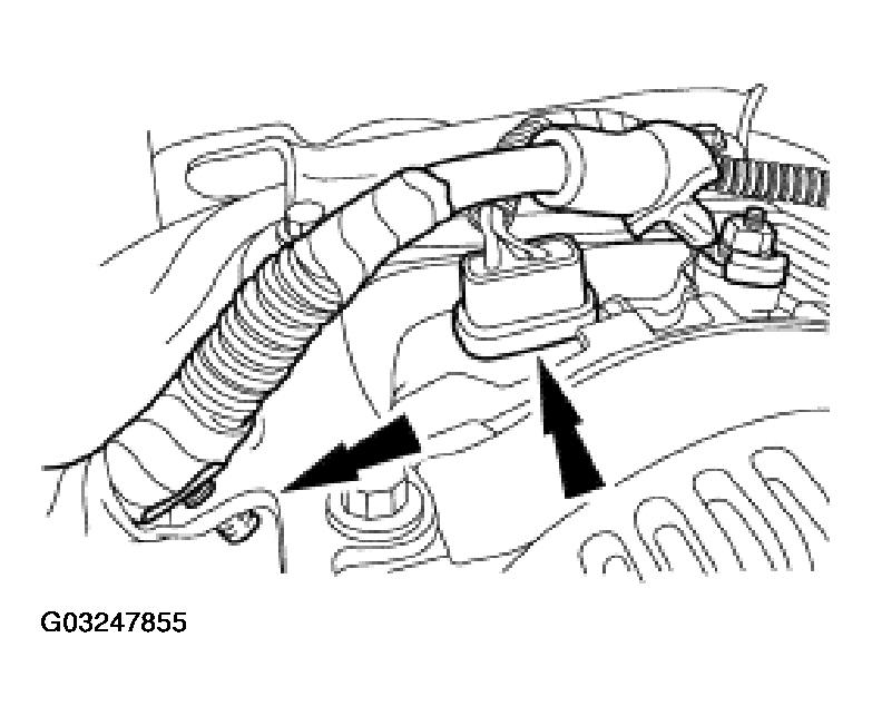
- Disconnect the upper radiator hose.
 Courtesy of FORD MOTOR CO.
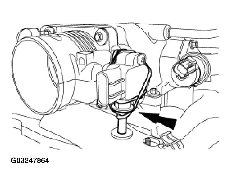
- Disconnect the idle air control (IAC) valve and the throttle position (TP) sensor electrical connectors.
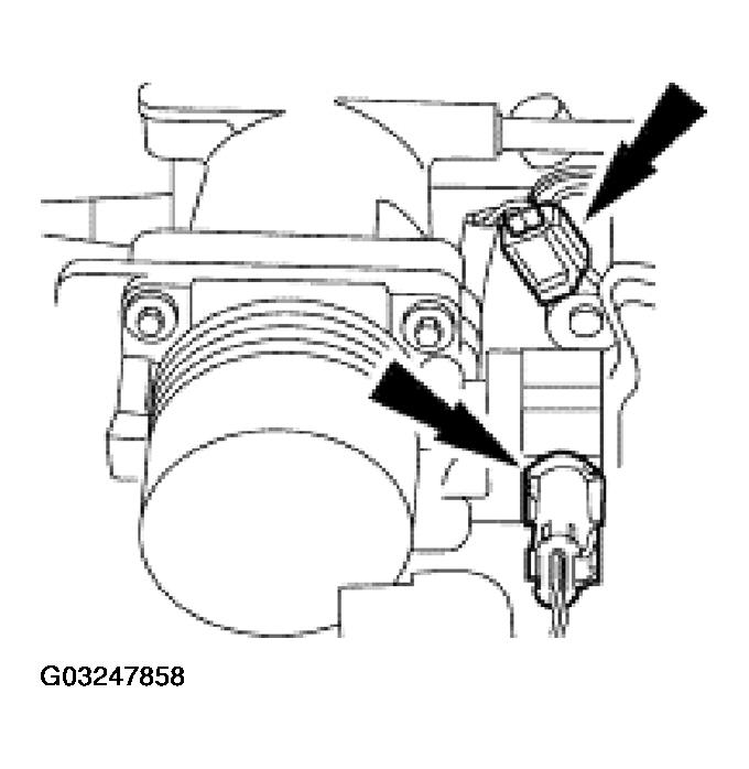 Courtesy of FORD MOTOR CO.
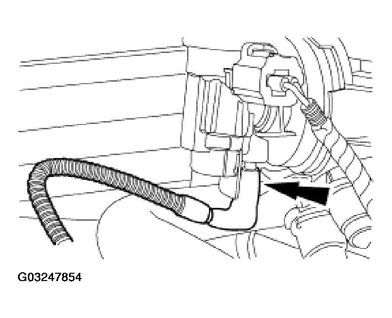
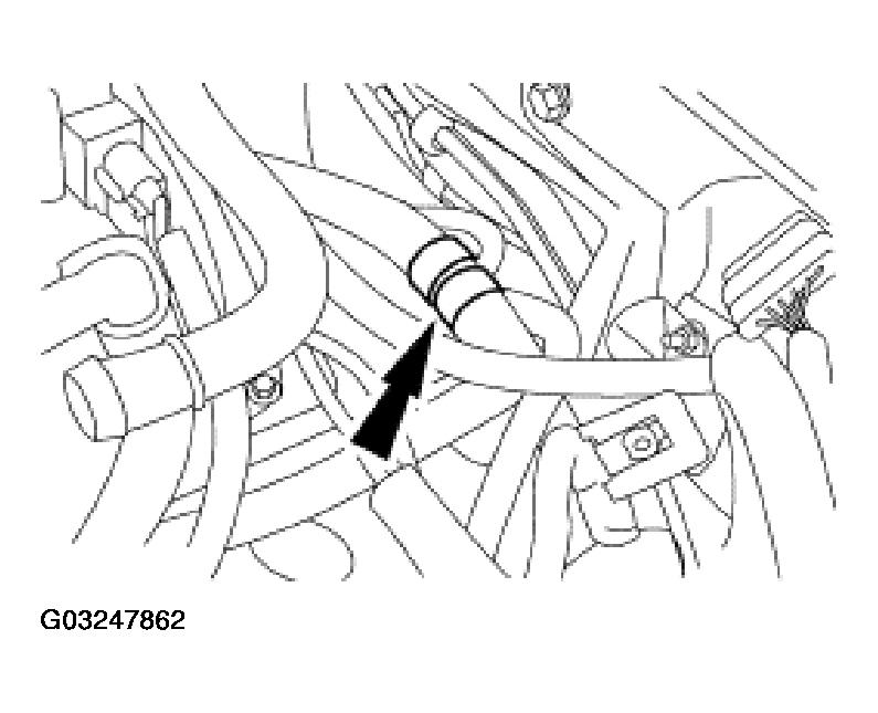
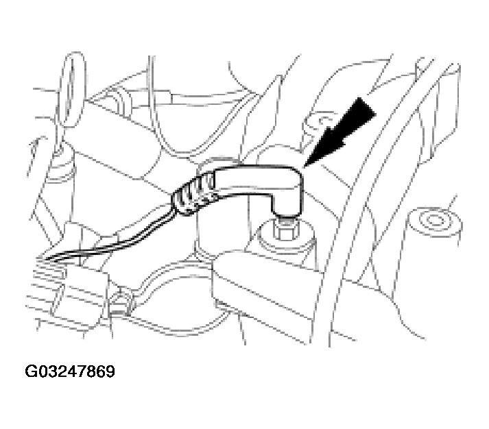
- Disconnect the heater hose.
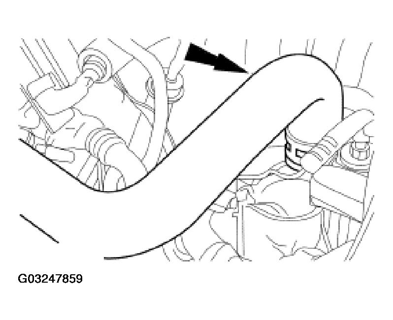 Courtesy of FORD MOTOR CO.
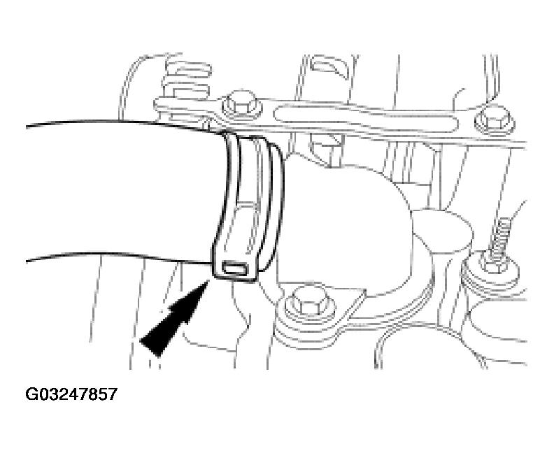
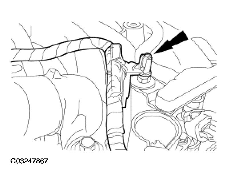
- Disconnect the EGR system module tube nut from the EGR system module.
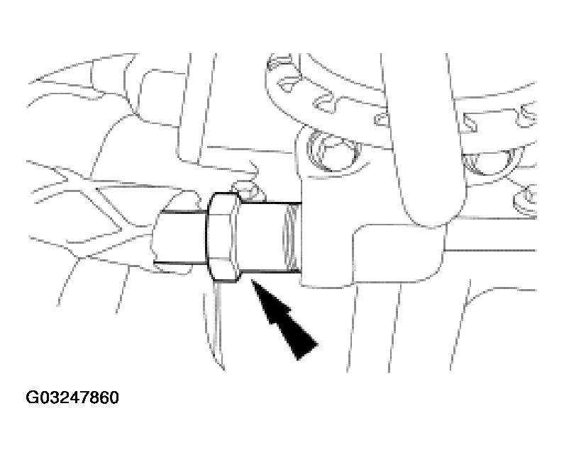 Courtesy of FORD MOTOR CO.
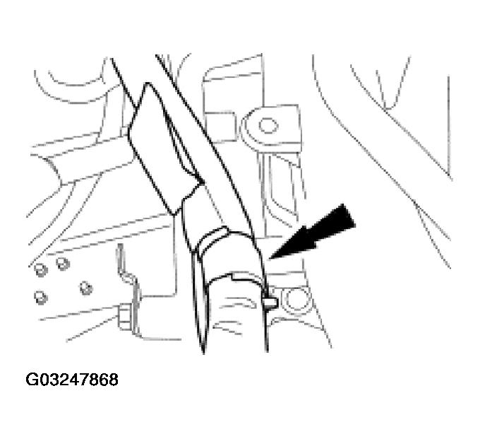
- Remove the nut at the exhaust manifold and remove the EGR tube.
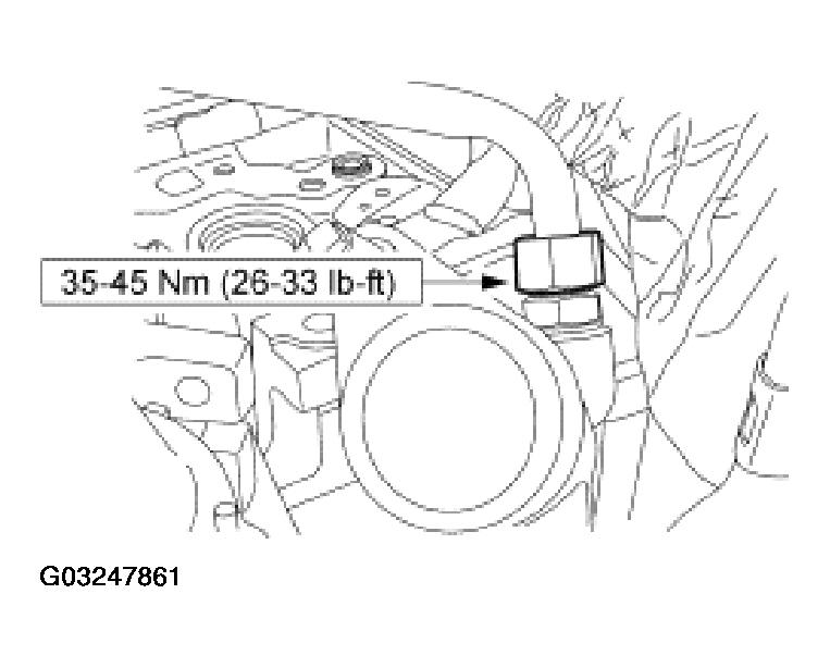 Courtesy of FORD MOTOR CO.
- Separate the fuel charging wiring pin-type retainer from the crash bracket.
 Courtesy of FORD MOTOR CO.
- Remove the cables from the crash bracket.
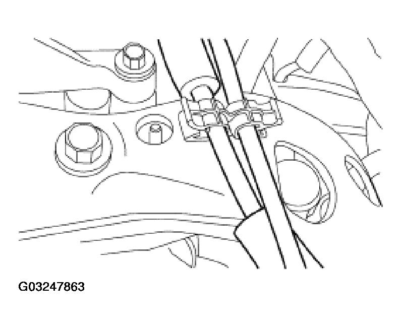 Courtesy of FORD MOTOR CO.
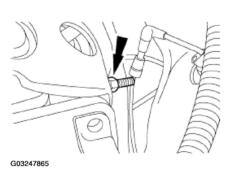
- Remove the crash bracket bolt and prevent the bolt from contacting the cylinder head with a rubber band or tie strap.
 Courtesy of FORD MOTOR CO.
- Remove the stud.
 Courtesy of FORD MOTOR CO.
- Disconnect the fuel pressure sensor electrical connector and the vacuum hoses.
 Courtesy of FORD MOTOR CO.
- Remove the generator harness position retainer from the LH front stud.
 Courtesy of FORD MOTOR CO.
- Remove the fuel charging wiring pin-type retainer from the rear of the manifold.
 Courtesy of FORD MOTOR CO.
- Disconnect the ground wire connector from the RH rear stud.
 Courtesy of FORD MOTOR CO.
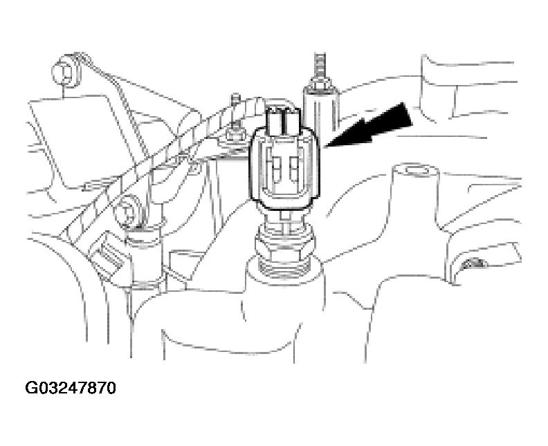
- Disconnect the coolant temperature sensor electrical connector.
 Courtesy of FORD MOTOR CO.
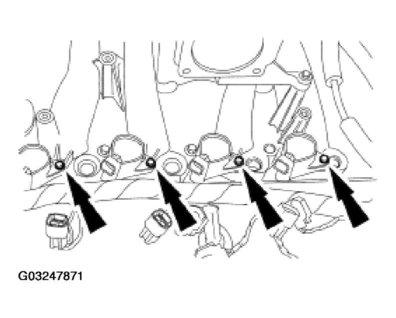
- Remove the bolts and the eight ignition coils.
 Courtesy of FORD MOTOR CO.
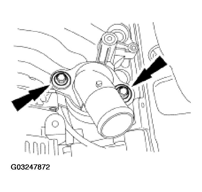
- Remove the bolts and the coolant outlet adapter.
 Courtesy of FORD MOTOR CO.
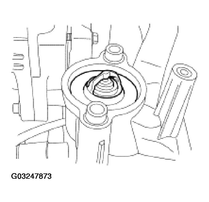
- Remove the thermostat and discard the O-ring.
 Courtesy of FORD MOTOR CO.
- Remove the bolts and the intake manifold.
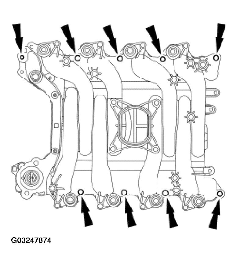 Courtesy of FORD MOTOR CO.
- Remove and discard the intake manifold gaskets.
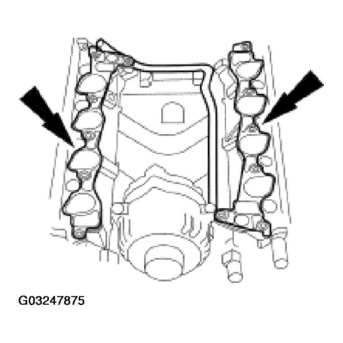 Courtesy of FORD MOTOR CO.
- Clean the sealing surfaces.
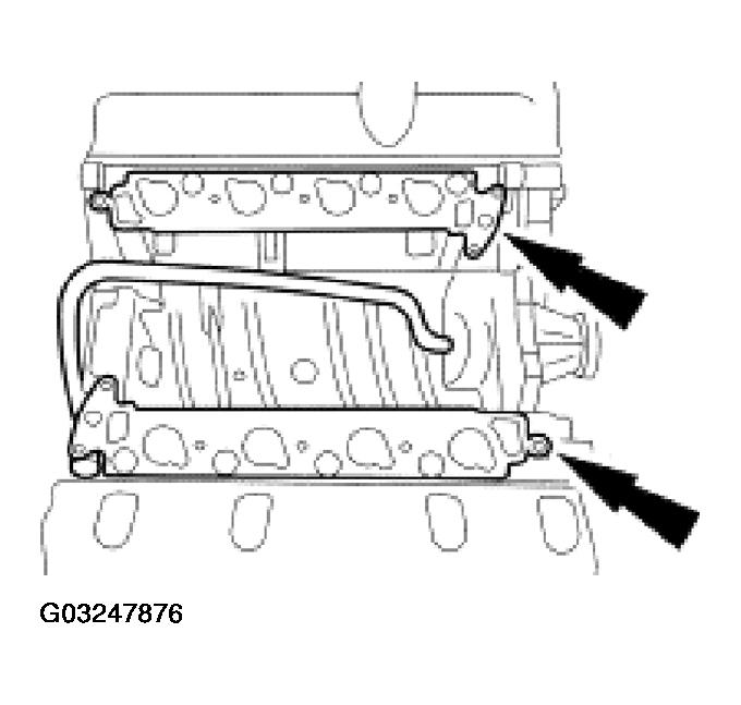 Courtesy of FORD MOTOR CO.