Test A: Engine Does Not Crank
- Perform Powertrain Control Module (PCM) self test. The Passive Anti-Theft System (PATS) DTCs are the only DTCs of concern in this step. If no PATS DTCs are present, go to next step. If any PATS DTCs are present, repair as necessary. See PASSIVE ANTI-THEFT SYSTEMS article in ACCESSORIES & EQUIPMENT.
- Verify battery condition. Battery voltage should be 12 volts or more. Load test battery at approximately one-half cold cranking amperage rating. See load tester manufacturer's instructions. If battery voltage is less than 12 volts or loaded battery voltage is less than 9.6 volts, service battery or charging system as necessary. If battery is okay, go to next step.
- Measure voltage between ground cable connection on cylinder block and positive battery terminal. If voltage is more than 10 volts, go to next step. If voltage is 10 volts or less, replace negative battery cable. Restore electrical connections and check system operation.
- Measure voltage between positive battery terminal and starter motor case. If voltage is more than 10 volts, go to next step. If voltage is 10 volts or less, ensure starter motor is correctly mounted and grounded. Restore electrical connections and check system operation.
- Measure voltage between ground and terminal "B" (battery positive cable connection) on starter solenoid. If voltage is more than 10 volts, go to next step. If voltage is 10 volts or less, replace positive battery cable. Restore electrical connections and check system operation.
- Connect a remote starter switch between starter solenoid terminals "B" and "S" (Yellow/Light Blue wire) on starter solenoid. Operate remote starter switch. If starter engages and engine cranks, go to next step. If starter motor does not operate, replace starter motor. Restore electrical connections and check system operation.
- Disconnect starter solenoid terminal "S" (Yellow/Light Blue wire) harness connector. Hold ignition switch in START position while measuring voltage between "S" terminal harness connector and ground. If voltage is less than 10 volts, go to next step. If voltage is more than 10 volts, clean "S" terminal wire connector and check Yellow/Light Blue wire for intermittent open. Restore electrical connections and check system operation.
- Turn ignition off. Remove starter relay located in the battery junction box. The battery junction box is located on the right side of engine compartment, on fenderwell. See Figure
. Hold ignition switch in START position while measuring voltage between ground and starter relay connector terminal No. 86. If voltage is more than 10 volts, go to next step. If voltage is 10 volts or less, go to step 13
.
- Turn ignition off. Measure voltage between ground and starter relay connector terminal No. 30. If voltage is 10 volts or more, go to next step. If voltage is less than 10 volts, repair open Yellow wire between battery junction box and starter relay harness connector. See WIRING DIAGRAMS
. Restore electrical connections and check system operation.
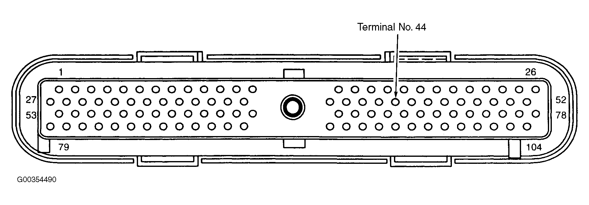
- Disconnect the Powertrain Control Module (PCM) harness connector. The PCM is located in the left rear of engine compartment. Measure the resistance between starter relay connector terminal No. 85 Gray/Red wire and PCM connector terminal No. 44 Gray/Red. See Fig 1
. If resistance is less than 5 ohms, go to next step. If resistance is 5 ohms or more, repair open in Gray/Red wire between starter relay terminal No. 85 and PCM connector. See WIRING DIAGRAMS
. Restore electrical connections and check system operation.
- Disconnect starter solenoid terminal "S" (Yellow/Light Blue wire) harness connector. Measure resistance between ground and starter relay harness connector terminal No. 87. If resistance is 10 k/ohms or more, go to next step. If resistance is less than 10 k/ohms, repair short to ground in Yellow/Light Blue wire between starter relay and ground. See WIRING DIAGRAMS
. Restore electrical connections and check system operation.
- Measure resistance in Yellow/Light Blue wire between starter relay connector terminal No. 87 and starter solenoid "S". If resistance is less than 5 ohms, install a new starter relay. Test the system for normal operation. If resistance is 5 ohms or more, repair open Yellow/Light Blue wire. See WIRING DIAGRAMS
. Restore electrical connections and check system operation.
- Turn ignition off. Remove fuse No. 26 (5-amp) in central junction box. Measure the resistance of fuse No. 26 in central junction box. See Figure
. If the resistance of fuse No. 26 is 0 ohms, the fuse is okay, go to next step. If the resistance is not 0 ohms, go to step 20
.
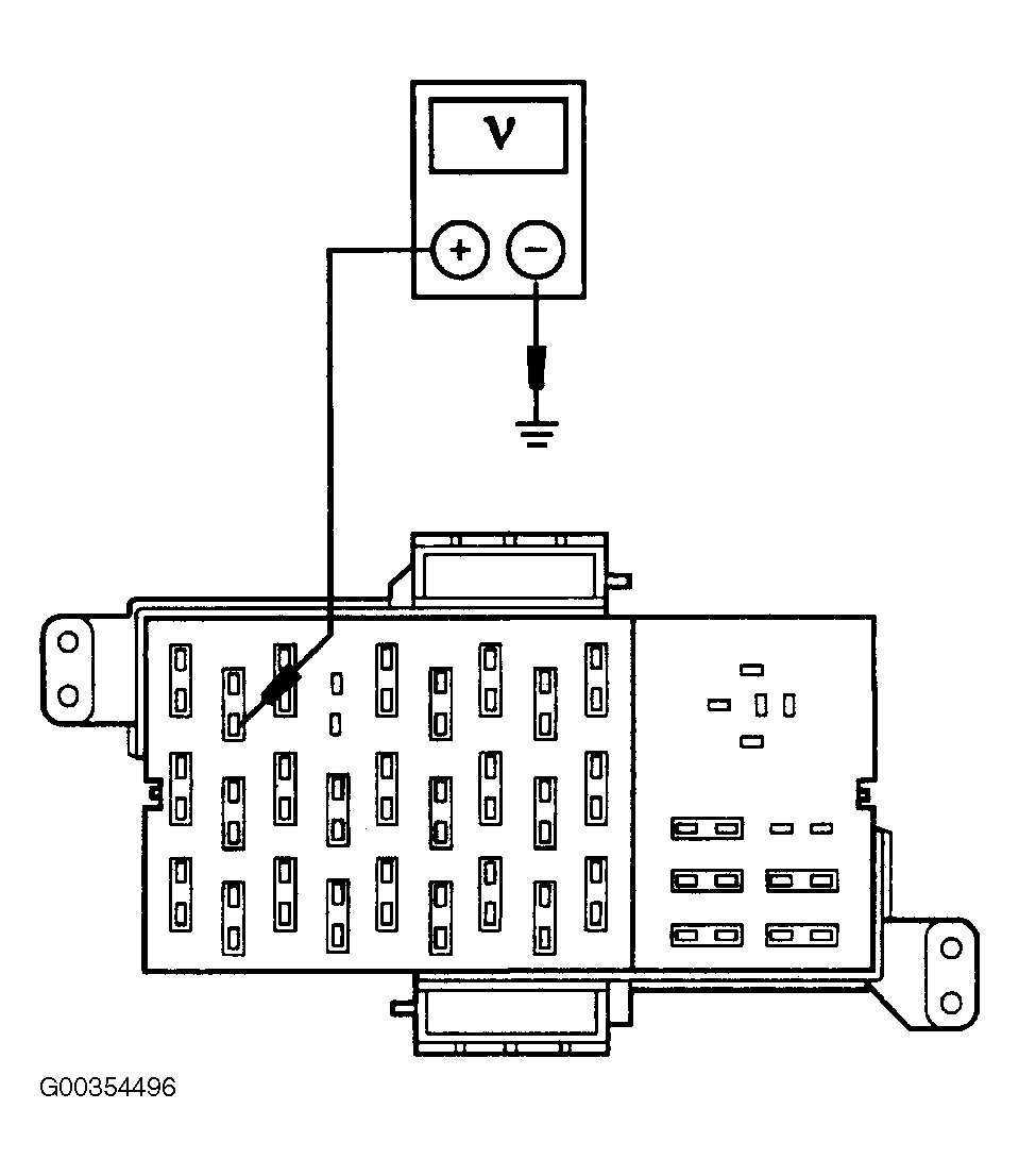
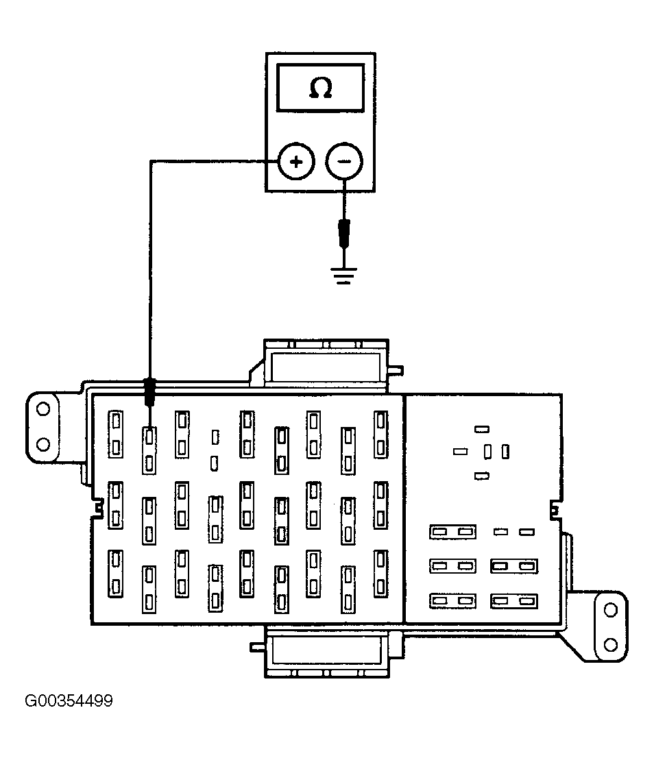
- Measure voltage between ground and central junction box fuse No. 26 (input side) while holding ignition switch in START position. See Fig 2
. If voltage is 10 volts or less, go to next step. If voltage is more than 10 volts, go to step 18
.
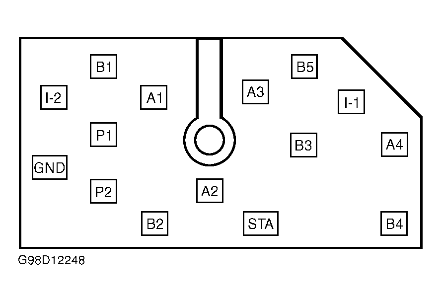
- Turn ignition switch to off position. Disconnect ignition switch harness connector. Measure voltage between ground and ignition switch harness connector terminal B4 (Yellow wire). See Fig 3
. If voltage is more than 10 volts, go to next step. If voltage is 10 volts or less, repair open in Yellow wire between ignition switch and battery junction box. See WIRING DIAGRAMS
. Restore electrical connections and check system operation.
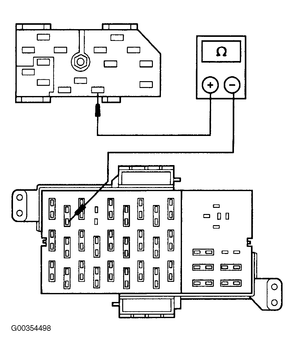
- Measure resistance between ignition switch harness connector terminal STA and central junction box fuse No. 26 (input side). See Fig 4
. If resistance is less than 5 ohms, go to next step. If resistance is 5 ohms or more, repair open Red/Light Blue wire. See WIRING DIAGRAMS
. Restore electrical connections and check system operation.
- Measure resistance between ground and ignition switch harness connector terminal STA (Red/Light Blue wire). See Fig 3
. If resistance is more than 10 k/ohms, replace ignition switch. See STEERING COLUMN SWITCHES article in ACCESSORIES & EQUIPMENT. If resistance is 10 k/ohms or less, repair short to ground in Red/Light Blue wire. See WIRING DIAGRAMS
. Restore electrical connections and check system operation.
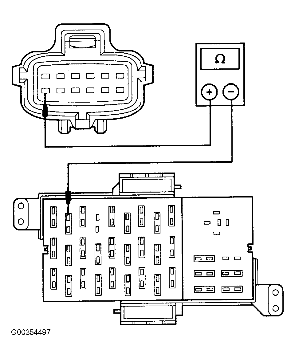
- Disconnect Digital Transmission Range (DTR) sensor harness connector. Measure resistance of Brown/Pink wire between DTR sensor harness connector terminal No. 12 and central junction box fuse No. 26 (output side). See Fig 5
. If resistance is less than 5 ohms, go to next step. If resistance is 5 ohms or more, repair open in Brown/Pink wire between central junction box and DTR sensor connector. See WIRING DIAGRAMS
. Restore electrical connections and check system operation.
- Measure resistance of White/Pink wire between DTR sensor harness connector terminal No. 10 and starter relay harness connector terminal No. 86. See Fig 7
. If resistance is 5 ohms or more, repair open in White/Pink wire. See WIRING DIAGRAMS
. If resistance is less than 5 ohms, check DTR sensor adjustment. See DIGITAL TRANSMISSION RANGE SENSOR
under ADJUSTMENTS. If adjustment is okay, replace DTR sensor. Restore electrical connections and check system operation.
- Remove starter relay from battery junction box. The battery junction box is located left side of engine compartment, on fenderwell. Measure resistance between ground and central junction box fuse No. 26 (output side). See Fig 6
. If resistance is less than 10 k/ohms, go to next step. If resistance is 10 k/ohms or more, visually inspect wires for damage that may cause an intermittent connection to ground. Replace starter relay and fuse. Check system for normal operation.
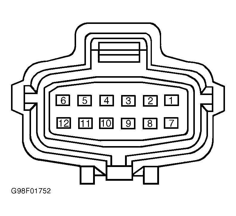
- Disconnect Digital Transmission Range (DTR) sensor harness connector. Measure resistance between ground and DTR sensor harness connector terminal No. 12 (Brown/Pink wire). See Fig 7
. If resistance is more than 10 k/ohms, go to next step. If resistance is 10 k/ohms or less, repair short to ground in circuit between DTR sensor and starter relay. See WIRING DIAGRAMS
. Restore electrical connections and check system operation.
- Measure resistance between ground and DTR sensor harness connector terminal No. 10 (White/Pink wire). See Fig 7
. If resistance is more than 10 k/ohms, replace DTR sensor. If resistance is 10 k/ohms or less, repair short to ground in White/Pink wire. See WIRING DIAGRAMS
. Restore electrical connections and check system operation.
 Courtesy of FORD MOTOR CO.
 Courtesy of FORD MOTOR CO.
 Courtesy of FORD MOTOR CO.
 Courtesy of FORD MOTOR CO.
 Courtesy of FORD MOTOR CO.
 Courtesy of FORD MOTOR CO.
 Courtesy of FORD MOTOR CO.