Test A: No Communication With Lighting Control Module
- Turn ignition off. Connect New Generation Star (NGS) tester. Turn ignition switch to RUN position. Using NGS tester, monitor LCM PID IGN_LC. If NGS tester displays UNABLE TO PERFORM TEST/FUNCTION - MODULE NOT RESPONDING: LCM - CHECK IGNITION STATUS/VERIFY CABLE REQUIREMENTS - CHECK CABLE CONNECTION, go to step 8
. If NGS tester display is not as specified, go to next step.
- Using NGS tester, monitor LCM PID IGN_LC while rotating ignition switch through ACC, OFF, and RUN positions. If PID IGN_LC does not indicate OFF while in all positions, go to next step. If PID IGN_LC indicates OFF while in all positions, go to step 5
.
- Using a voltmeter, check voltage between ground and output side (top terminal) of fuse junction panel fuse No. 14 (7.5-amp). If voltage is 10 volts or less, go to next step. If voltage is more than 10 volts, repair Red/Yellow wire between fuse junction panel fuse No. 14 and LCM and retest system operation.
- Check fuse junction panel fuse No. 14 (7.5-amp). If fuse is okay, repair White/Yellow wire between fuse junction panel and ignition switch and retest system operation. If fuse is not okay, repair Red/Yellow wire between fuse junction panel fuse No. 14 and LCM. Replace fuse and retest system operation.
- Using a voltmeter, check voltage between ground and output side (top terminal) of fuse junction panel fuse No. 18 (7.5-amp). If voltage is more than 10 volts, go to next step. If voltage is 10 volts or less, go to step 7
.
- Turn ignition off. Disconnect LCM 12-pin connector C220 located behind center of instrument panel. Turn ignition switch to RUN position. Using a voltmeter, check voltage between ground and LCM 12-pin connector C220, terminal No. 6 (Dark Blue/Light Green wire). See Fig 1
. If voltage is more than 10 volts, replace LCM and retest system operation. If voltage is 10 volts or less, repair Dark Blue/Light Green wire between fuse junction panel fuse No. 18 and LCM and retest system operation.
- Check fuse junction panel fuse No. 18 (7.5-amp). If fuse is okay, repair Black/Light Green wire between fuse junction panel and ignition switch and retest system operation. If fuse is not okay, repair Dark Blue/Light Green wire between fuse junction panel fuse No. 18 and LCM. Replace fuse and retest system operation.
- Using a voltmeter, check voltage between ground and output side (left terminal) of fuse junction panel fuse No. 31 (7.5-amp). If voltage is 10 volts or less, go to next step. If voltage is more than 10 volts, go to step 12
.
- Check fuse junction panel fuse No. 31 (7.5-amp). If fuse is okay, repair Dark Blue/Orange wire between fuse junction panel and power distribution box and retest system operation. If fuse is not okay, go to next step.
- Turn ignition off. Remove and disconnect headlight switch. Disconnect LCM 16-pin connector C221 located behind center of instrument panel. Using an ohmmeter, check resistance between ground and LCM 16-pin connector C221, terminal No. 25 (Orange/White wire). See Fig 1
. If resistance is more than 10 k/ohms, go to next step. If resistance is 10 k/ohms or less, repair short to ground in Orange/White wire between fuse junction panel fuse No. 31 and LCM and retest system operation.
- Connect and install headlight switch. Using an ohmmeter, check resistance between ground and LCM 16-pin connector C221, terminal No. 25 (Orange/White wire). If resistance is more than 10 k/ohms, go to next step. If resistance is 10 k/ohms or less, replace headlight switch and retest system operation.
- Disconnect LCM 16-pin connector C221 located behind center of instrument panel. Using a voltmeter, check voltage between ground and LCM 16-pin connector C221, terminal No. 25 (Orange/White wire). See Fig 1
. If voltage is more than 10 volts, go to next step. If voltage is 10 volts or less, repair open in Orange/White wire between fuse junction panel fuse No. 31 and LCM and retest system operation.
- Disconnect LCM 13-pin connector C222 located behind center of instrument panel. Ensure ignition is off. Using an ohmmeter, check resistance between ground and LCM 16-pin connector C221 terminal No. 23 (Pink/Orange wire). See Fig 1
. Check resistance between ground and LCM 13-pin connector C222, terminal No. 13 (Pink/Orange wire). If both resistances are less than 5 ohms, see appropriate MODULE COMMUNICATIONS NETWORK article to continue diagnosis. If either resistances is 5 ohms or more, repair open in appropriate Pink/Orange wire between LCM and ground and retest system operation.
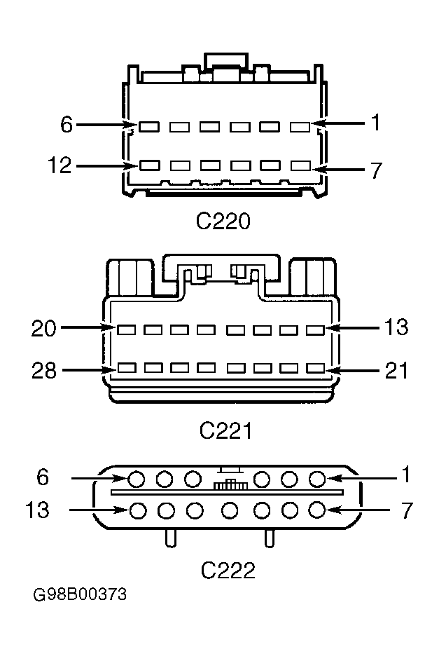 Courtesy of FORD MOTOR CO.