Test B: No Communications With Rear Electronic Module (Rem)
- Ensure ignition switch is in LOCK position. Disconnect Rear Electronic Module (REM) harness connectors C420c and C420d. Turn ignition switch to RUN position. Measure voltage between REM 20-pin harness connector C420d terminal No. 3 (Orange/Black wire) and ground. See Fig 1
. If voltage is greater than 10 volts, go to next step. If voltage is less than 10 volts, repair open in Orange/Black wire and retest system operation.
- Turn ignition switch to LOCK position. Disconnect REM 22-pin harness connector C420b. Measure resistance between ground and Black wires at REM harness connectors C420c terminals No. 11, 12, 25 and 26. See Fig 2
. Measure resistance between REM 22-pin harness connector C420b terminal No. 12 (Black wire). See Fig 3
. Measure resistance between REM 26-pin harness connector C420c terminal No. 13 (Orange/Black wire) and ground. If resistances are less than 5 ohms, repair module communications concern. See MODULE COMMUNICATIONS NETWORK - LS article. If any resistance is greater than 5 ohms, repair open in appropriate wire and retest system operation.
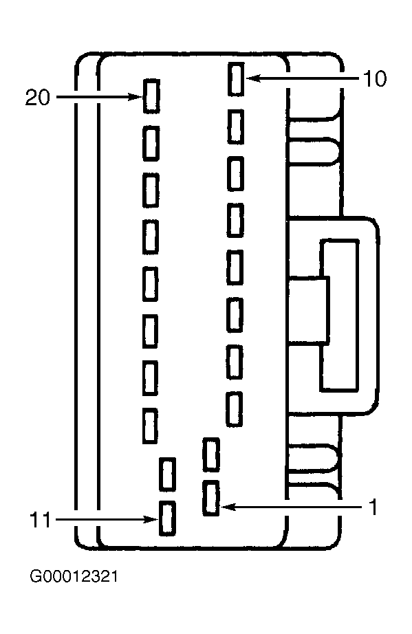 Courtesy of FORD MOTOR CO.
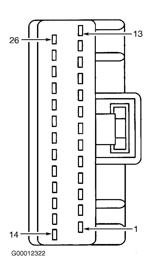 Courtesy of FORD MOTOR CO.
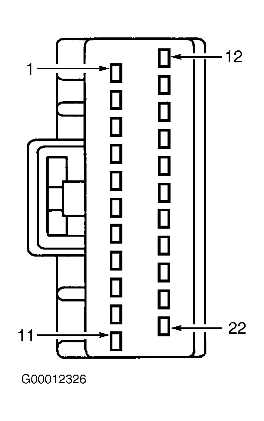 Courtesy of FORD MOTOR CO.