Starter Does Not Crank
- Check Battery State Of Charge
Turn ignition off. Turn headlights on for 10 seconds to remove surface charge. Turn headlights off. Measure voltage between battery terminals. If battery voltage is 12.4 volts or more, go to next step. If battery voltage is less than 12.4 volts, service battery or charging system as necessary.
- Check Negative Battery Cable
Measure voltage between positive battery post and negative battery cable connection on engine. If battery voltage exists, go to next step. If less than battery voltage exists, replace negative battery cable. Check system operation.
- Check Starter Motor Ground
Measure voltage between positive battery post and starter motor case. If battery voltage exists, go to next step. If less than battery voltage exists, remove starter and clean starter motor mounting surface. Install starter and check operation.
- Check Positive Battery Cable
Measure voltage between starter solenoid "B" (positive battery cable) terminal and ground. If battery voltage exists, go to next step. If less than battery voltage exists, clean terminals or replace battery cable as necessary. Restore electrical connections and check system operation.
- By-Pass Switch Circuit
Connect a remote starter switch between starter solenoid "B" and "S" terminals. See Figure
. Activate remote starter switch. If starter cranks at normal speed, go to next step. If starter motor does not crank, replace starter motor and solenoid. Restore electrical connections and check system operation.
- Check Start Signal
Disconnect White/Pink wire from starter solenoid. Hold ignition switch in START position. Measure voltage between ground and White/Pink wire at starter solenoid. If battery voltage does not exist, go to next step. If battery voltage exists, ensure "S" terminal connection is clean and tight. If okay, replace starter.
- Check Start Signal To Starter Relay
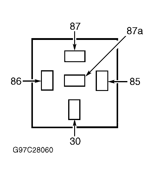
Turn ignition off. Remove starter relay. Hold ignition switch in START position. Measure voltage between ground and starter relay harness connector terminal No. 86 (Tan/Red wire). See Fig 1
. If battery voltage exists, go to next step. If battery voltage does not exist, go to step 12).
 Courtesy of FORD MOTOR CO.
- Check Voltage To Starter Relay
Turn ignition off. Measure voltage between starter relay harness connector terminal No. 30 (Yellow/Light Blue wire). If battery voltage exists, go to next step. If battery voltage does not exist, repair open Yellow/Light Blue wire. Restore electrical connections and check system operation.
- Check Starter Relay Ground
Measure resistance between starter relay harness connector terminal No. 85. If resistance is less than 5 ohms, go to next step. If resistance is greater than 5 ohms, repair open Black wire. Restore electrical connections and check system operation.
- Check White/Pink Wire For Short To Ground
Disconnect White/Pink wire from starter solenoid. Measure resistance between ground and starter relay harness connector terminal No. 87 (White/Pink wire). If resistance is greater than 10 k/ohms, go to next step. If resistance is less than 10 k/ohms, repair White/Pink wire for short to ground. Restore electrical connections and check system operation.
- Check White/Pink Wire For Open
Measure resistance of White/Pink wire between starter relay harness connector terminal No. 87 and White/Pink wire at starter solenoid. If resistance is less than 5 ohms, replace starter relay. If resistance is greater than 5 ohms, repair open White/Pink wire. Restore electrical connections and check system operation.
- Check Fuse No. 23
Check fuse No. 23 in instrument panel fuse panel. If fuse is okay, go to next step. If fuse is blown, go to step 19).
- Check Start Signal To Fuse No. 23
Hold ignition switch in START position. Measure voltage between input side of fuse cavity No. 23. If battery voltage does not exist, go to next step. If battery voltage exists, go to step 17).
- Check Voltage To Ignition Switch
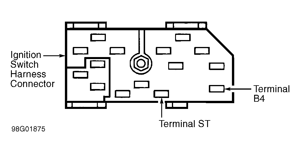
Disconnect ignition switch harness connector. Measure voltage between ground and ignition switch harness connector terminal B4 (Black/Orange wire). See Fig 2
. If battery voltage exists, go to next step. If battery voltage does not exist, check all fuses in underhood fuse box. If fuses are okay, repair open Black/Orange wire. Restore electrical connections and check system operation.
 Courtesy of FORD MOTOR CO.
- Check Red/Light Blue Wire For Open
Measure resistance of Red/Light Blue wire between fuse cavity No. 23 and ignition switch harness connector terminal ST. See Fig 2
. If resistance is less than 5 ohms, go to next step. If resistance is greater than 5 ohms, repair open Red/Light Blue wire. Restore electrical connections and check system operation.
- Check Red/Light Blue Wire For Short To Ground
Measure resistance between ignition switch harness connector terminal ST and ground. If resistance is less than 10 k/ohms, repair Red/Light Blue wire for short to ground. If resistance is greater than 10 k/ohms, replace ignition switch. Restore electrical connections and check system operation.
- Check White/Orange Wire For Open
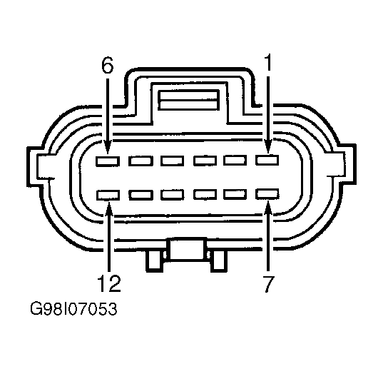
Disconnect Transmission Range (TR) sensor. Measure resistance of White/Orange wire between TR sensor harness connector terminal No. 10 and fuse cavity No. 23 in instrument panel fuse panel. See Fig 3
. If resistance is less than 5 ohms, go to next step. If resistance is greater than 5 ohms, repair open White/Orange wire. Restore electrical connections and check system operation.
 Courtesy of FORD MOTOR CO.
- Check Tan/Red Wire For Open
Measure resistance of Tan/Red wire between TR sensor harness connector terminal No. 12 and starter relay harness connector terminal No. 86. See Fig 1
and Fig 3
. If resistance is greater than 5 ohms, repair open Tan/Red wire. If resistance is less than 5 ohms, check TR sensor adjustment. If TR sensor is in adjustment, replace TR sensor. Restore electrical connections and check system operation.
- Check White/Orange Wire For Short
Measure resistance of White/Orange wire between ground and fuse cavity No. 23 in instrument panel fuse panel. If resistance is less than 10 k/ohms, go to next step. If resistance is greater than 10 k/ohms, inspect wires for possible intermittent short to ground. Replace fuse and check system operation.
- Check White/Orange Wire For Short To Ground
Disconnect TR sensor harness connector. Measure resistance between TR sensor harness connector terminal No. 10 and ground. See Fig 3
. If resistance is greater than 10 k/ohms, go to next step. If resistance is less than 10 k/ohms, repair White/Orange wire for short to ground. Restore electrical connections and check system operation.
- Check Tan/Red Wire For Short To Ground
Measure resistance between TR sensor harness connector terminal No. 12 and ground. If resistance is greater than 10 k/ohms, check TR sensor adjustment. If TR sensor is in adjustment, replace TR sensor. If resistance is less than 10 k/ohms repair Tan/Red wire for short to ground. Restore electrical connections and check system operation.