Test F: Sensor Faulty
- Disconnect motor and sensor harness leads from the power seat assembly.
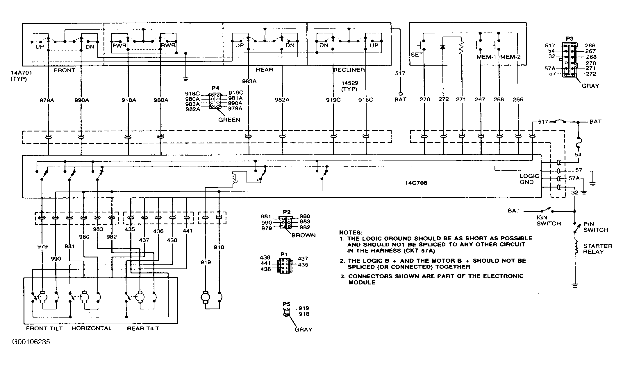
- Connect together terminals No. 437 and 266 of Connectors P1 and P3, respectively. Then connect together terminals No. 435 and Pin 57A of the same connectors. See Fig 1
. Leave Connector P3 attached. Using an ohmmeter, connect the ground of the ohmmeter to terminal No. 57A and the resistance input to terminal No. 438 of Connector P1
- Attach two leads from terminals No. 980 and 981 of Connector P2. Connect the other end of one lead to terminal No. 517 of Connector P3. Tap the free lead to terminal No. 57 of the same connector. The power seat track assembly should move. If not, reverse the leads.
- Continue a pattern of tapping a lead to move the track assembly, while observing the reading of the ohmmeter in between movements. It should be possible to observe an open circuit resistance and a resistance of less than 20 ohms.
- If the sensor resistance remains consistently open or less than 20 ohms after moving the track assembly through a few cycles, then the sensor is inoperative and the sensor assembly should be replaced.
- Repeat the above steps starting with Step 2 for the remaining two sensors, if necessary. For the second sensor, use terminal No. 441 instead of terminals No.438 in step 2
and terminals No. 979 and 990 instead of terminals No. 980 and 981 in step 3
. For the third sensor, use terminal No. 436 instead of terminals No. 438 in step 2
and terminals No. 979 and 990 instead of terminals No. 980 and 981 in step 3
.
- If the ohmmeter reads open circuit and less than 20 ohms, then the sensor is functioning properly at this time. Check for damaged connectors, shorts or open circuit. Repair as necessary. Go to TEST D: TRACK DOES NOT MOVE HORIZONTALLY AND/OR VERTICALLY
. If ohmmeter reads open circuit or less than 20 ohms consistently, replace the sensor assembly.
 Courtesy of FORD MOTOR CO.