Control Module Test
- Connect voltmeter between terminal No. 6 of control module and ground. See Fig 1
. Turn ignition switch to RUN position, with engine off. Battery voltage should be present.
- If no voltage present, check fuse and wiring from ignition switch. If battery voltage is present, go to step 3).
- Connect voltmeter between terminal No. 12 of control module and ground. Turn ignition off. Battery voltage should be present.
- If voltage is greater than zero but less than 10, replace control module. If reading is zero volts, check wire from alternator output relay MOD terminal to control module. If battery voltage is present, go to step 5).
- With voltmeter connected as in step 4), start engine. Run engine at 1000-1500 RPM with no electrical load except windshield.
- Turn heated windshield switch to ON position and read voltmeter after 10 seconds. Voltage at terminal No. 12 should drop from battery voltage to about one volt a few seconds after windshield heat is turned on.
- If voltage drops to one volt, go to step 8). If voltage stays greater than 3 volts or less than 0.5 volt, replace control module.
- Connect voltmeter between terminal No. 10 of control module and ground. Run engine with no electrical load except windshield. Turn heated windshield switch to ON position, and read voltmeter after 10 seconds.
- If voltage is greater than 2 volts, repair windshield ground circuit. If less that .05 volts, repair wire between windshield and sense resistor. Recheck windshield for high resistance. If voltage is between .05 volts and 2 volts, system is okay.
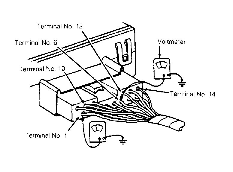 Courtesy of FORD MOTOR CO.