Transfer Case Disassembly
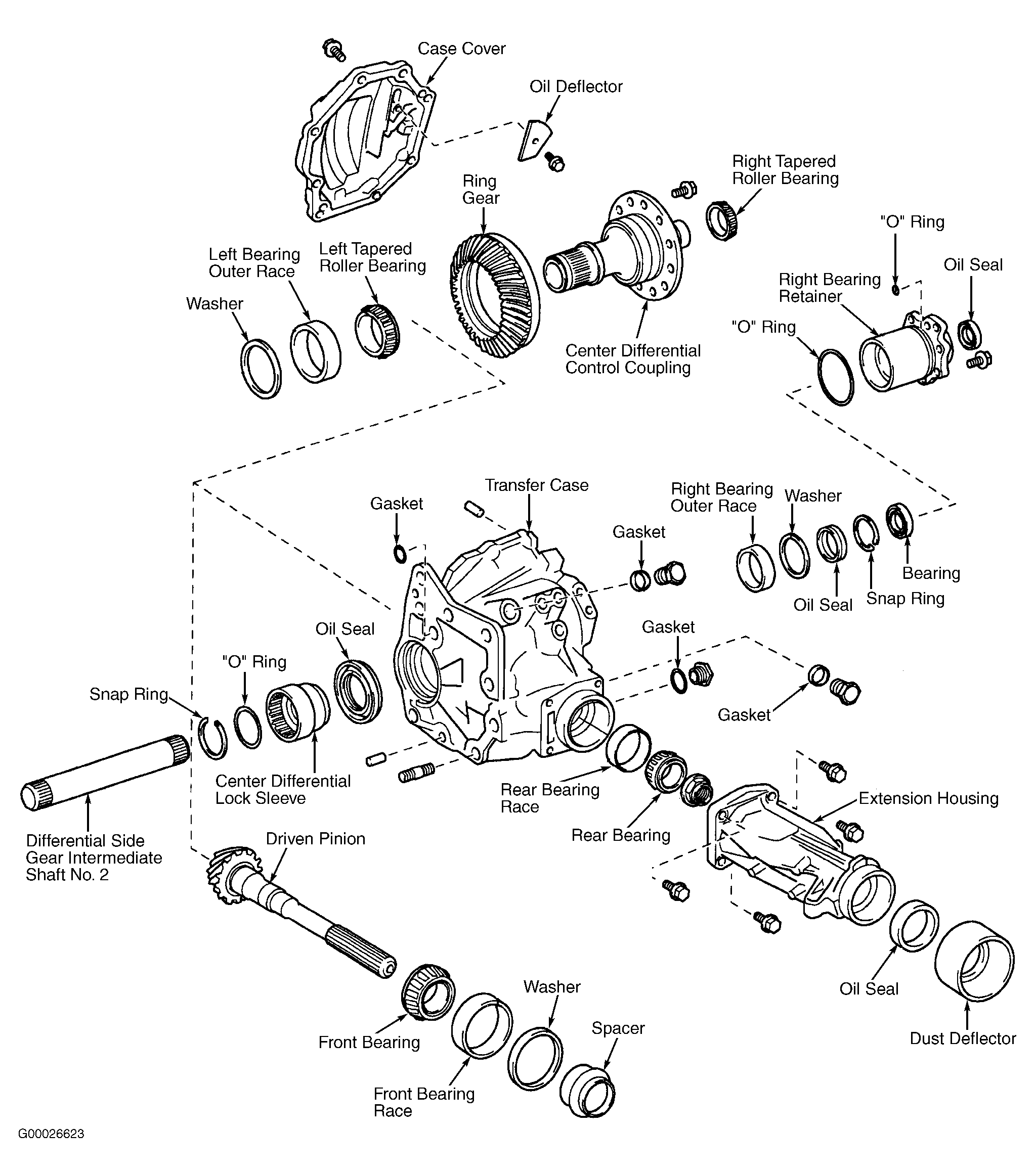
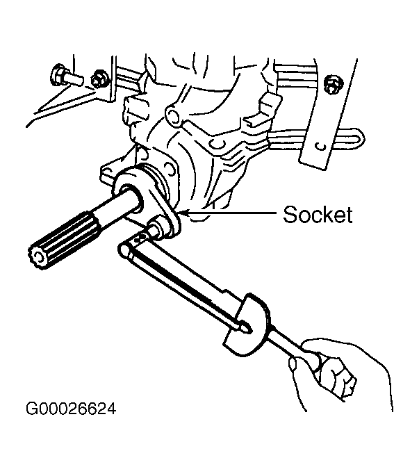
- Remove differential side gear intermediate shaft No. 2. Remove case cover. See Fig 1. Remove oil deflector from case cover. Remove extension housing. Check and record starting torque of driven pinion using Driven Pinion Nut Socket (09326-20011). See Fig 2. Starting torque should be 7.8-11.2 INCH lbs. (.9-1.3 N.m).
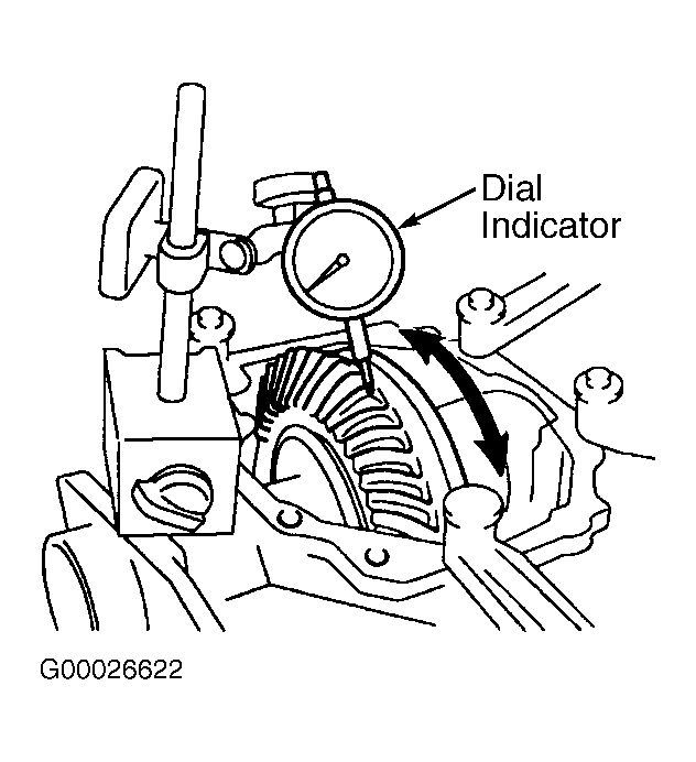
- Check and record ring gear backlash. Mount dial indicator on transfer case. See Fig 3. Backlash should be .004-.006" (.10-.15 mm). Remove center differential lock sleeve snap ring. Remove center differential lock sleeve using slide hammer with 2-jaw attachment. Remove "O" ring from center differential lock sleeve.
- Remove bearing retainer from right side of transfer case. Remove internal components from bearing retainer. See Fig 1. Remove center differential control coupling from transfer case. Using appropriate puller, remove bearing from center differential control coupling (as necessary). Place center differential control coupling on "V" blocks, and measure ring gear runout. Runout should not exceed .004" (.10 mm).
- Place match marks for reassembly reference on ring gear and center differential control coupling. Remove ring gear bolts in crisscross pattern. Using plastic faced hammer, remove ring gear. Place center differential control coupling on "V" blocks, and measure ring gear mounting face runout. Runout should not exceed .004" (.10 mm).
- Using hammer and chisel, unstake driven pinion lock nut. Remove lock nut. Press out driven pinion, rear bearing race and spacer. Remove remaining bearings and races (as needed).
 Courtesy of © TOYOTA, LICENSE AGREEMENT TMS1002
 Courtesy of © TOYOTA, LICENSE AGREEMENT TMS1002
 Courtesy of © TOYOTA, LICENSE AGREEMENT TMS1002