Heater Main Relay Circuit
- Turn ignition on. Inspect HEATER fuse, in fuse block, at driver's side kick panel. If fuse is okay, go next step. If fuse is blown, correct cause and replace fuse.
- Remove A/C control assembly, leaving harness connectors connected. Turn ignition off. Check for voltage between A/C control assembly connector terminal A14-10 (Blue/White wire) and ground. See Figure. If battery voltage does not exist, go to next step. If battery voltage exists, repair short to voltage in Blue/White wire between connector and heater main relay.
- Turn ignition on. Check for voltage between A/C control assembly connector terminal A14-10 (Blue/White wire) and ground. If battery voltage does not exist, go to next step. If battery voltage exists, circuit is okay.
- Remove heater main relay, located behind glove box, on right side. Test for continuity between terminals No. 1 and 4. See Fig 1. Continuity should not exist. Test for continuity between terminals No. 2 and 4. Continuity should exist. Measure resistance between terminals No. 3 and 5. Resistance should be 62.5-90.9 ohms.
- Using a fused jumper wire, connect battery voltage to terminal No. 3, and connect terminal No. 5 to ground. Test for continuity between terminals No. 1 and 2. Continuity should exist. Test for continuity between terminals No. 2 and 4. Continuity should not exist. Replace relay if it does not operate as specified. If relay is okay, repair wiring between A/C control assembly connector and battery.
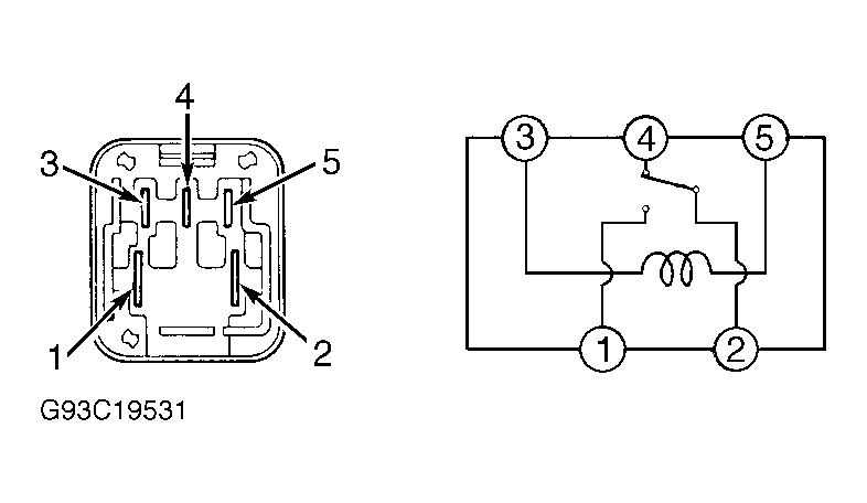 Courtesy of © TOYOTA, LICENSE AGREEMENT TMS1002