Compressor Circuit
- Turn ignition off. Gain access to Engine Control Module (ECM) connectors, leaving harness connectors connected. Backprobe between ECM 28-pin connector terminal E8-6 (Blue/Yellow wire) and ground. Start and run engine at idle and measure voltage.
- Push AUTO button and OFF button. See Figure. When AUTO button is pressed, voltage should be 10-14 volts. When OFF button is pressed, voltage should be zero. If voltage is as specified, go to next step. If voltage is not as specified, go to step 6.
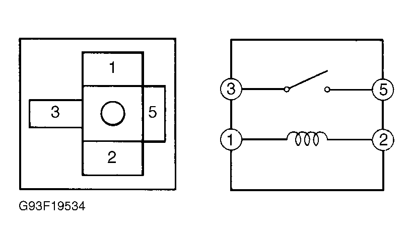
- Remove compressor clutch relay from relay box No. 5, located at left side of engine compartment, toward rear. Measure resistance between terminals No. 1 and 2. See Fig 1. Resistance should be 62.5-90.9 ohms. Test for continuity between terminals No. 3 and 5. Continuity should not exist.
- Using a fused jumper wire, connect battery voltage to terminal No. 1 of relay. Connect terminal No. 2 to ground. Test for continuity between terminals No. 3 and 5. Continuity should exist. If relay operates as specified, go to next step. Replace relay if continuity is not as specified.
- Unplug connector from compressor clutch. Using a fused jumper wire, connect battery voltage to compressor clutch connector terminal No. 3 (Black/White wire). If clutch engages, inspect wiring and connectors associated with compressor relay and compressor. Repair or replace wiring and connectors as necessary. If clutch does not engage, repair or replace compressor clutch.
- Turn ignition off. Unplug connector A15 from A/C control assembly. See Figure. Turn ignition on. Check for voltage at harness connector terminal A15-13 (Black/Yellow wire). If voltage is 10-14 volts, go to next step. If voltage is not 10-14 volts, substitute known-good ECM. Retest system.
- Turn ignition off. Reconnect A/C control assembly connector A15. Remove A/C control assembly, leaving harness connectors connected. See A/C CONTROL ASSEMBLY under REMOVAL & INSTALLATION. Start and run engine at idle. Backprobe between A/C control assembly connector terminal A15-13 (Black/Yellow wire) and ground. See Figure.
- Press AUTO button. Clutch should engage and voltage should be less than one volt. Press OFF button. Clutch should disengage and voltage should be 10-14 volts. If clutch operation and voltage is as specified, go to next step. If clutch operation and voltage are not as specified, substitute a known-good A/C control assembly, and retest. Replace A/C control assembly as necessary.
- Backprobe between terminal A15-10 (Black/White wire) of A/C control assembly connector and ground. Start engine. Press AUTO button. Clutch should engage and voltage should be 10-14 volts. Press OFF button. Clutch should disengage and voltage should be less than 1.5 volts. If clutch operation and voltage is as specified, inspect wiring and connectors between A/C control assembly and ECM. Repair as necessary. If clutch operation and voltage are not as specified, replace clutch and retest operation.
 Courtesy of © TOYOTA, LICENSE AGREEMENT TMS1002