Wiper Relay Circuit Test
- Turn ignition off. Disconnect wiper relay connector. Check for continuity between ground and terminal No. 15. See Fig 1. If continuity does not exist, repair circuit. If continuity exists, check resistance between terminals No. 14 and 18.
- Resistance should be about 50 ohms (interval switch SLOW) or less than 10 ohms (interval switch FAST). If resistance is okay, go to next step. If resistance is not okay, check for faulty circuits between wiper relay and wiper switch. If circuits are okay, replace wiper switch.
- Reconnect wiper control relay connector. Turn ignition on. Backprobing connector, measure voltage between chassis ground and terminals at wiper relay connector as specified. See Fig 1. See the WIPER RELAY CIRCUITS TEST table. If voltage is not as specified, repair faulty circuit or component.
WIPER RELAY CIRCUITS TEST
| Terminal No. (Wire Color) |
Voltage |
| 1 (Pink/Blue) |
| Wiper Off Or High |
Zero |
| Wiper Low Or Intermittent |
Battery |
| 2 (Red/Yellow) |
| Wiper Except HIGH |
Zero |
| Wiper High |
Battery |
| 3 (Light Green) |
| Wiper Except High |
Battery |
| Wiper High |
Zero |
| 4 (Blue/Black) |
| Wiper Off |
Zero |
| Wiper Low |
Battery |
| 5 (Blue/Orange), Wipers Operating |
Battery |
| 6 (Green) |
| Wiper High To Intermittent Or Low |
* |
| Wiper Intermittent Or Low To Off |
* |
| 7 (Voilet), Wipers Operating |
Battery |
| 8 (Blue) |
Battery |
| 9 (Red) |
| Wiper Off |
Battery |
| Wiper Intermittent Or Low |
Zero |
| Wiper High |
Battery |
| 10 (Light Green/Red) |
| Wiper Off |
Battery |
| Wiper Intermittent |
Zero |
| Wiper Low |
Battery |
| Wiper High |
Battery |
| 11 (Blue/Yellow) |
| Washer Off |
Battery |
| Washer On |
Zero |
| 13 (Blue/Red) |
| Concealment Switch FULL |
Battery |
| Concealment Switch SEMI |
Zero |
| 16 (Red/White) |
| Wiper Off To Intermittent Or Low |
* |
| Wiper Intermittent Or Low To High |
* |
| 17 (Voilet/Green) |
Zero |
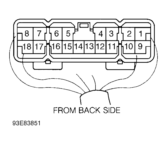 Courtesy of © TOYOTA, LICENSE AGREEMENT TMS1002