Installation Of Piston & Rod Assembly
- Locate applicable crankshaft journal at Bottom Dead Center (BDC).
- Place bearing upper shell in connecting rod. See Figure.
- Retain upper shell by screwing guide bolts (605351) onto connecting rods.
- Insert connecting rod and piston assembly into its respective bore, noting that domed shape boss on connecting rod must face toward front of engine on right-hand bank of cylinders and toward rear on left-hand bank. When both connecting rods are fitted, bosses will face inward toward each other. See Figure.
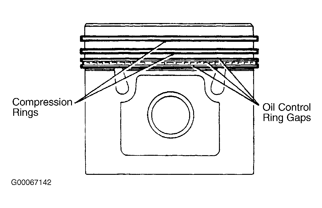
- Position oil control piston rings so that ring gaps are all at one side, between piston pin and piston thrust face. Space gaps in ring rails approximately 25 mm (1") each side of expander ring joint. See Fig 1.
- Position compression rings so that their gaps are on opposite sides of piston between piston pin and piston thrust face. See Fig 1.
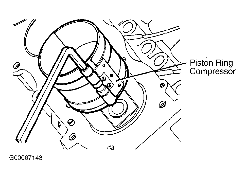
- Using a piston ring compressor, fit piston into cylinder bore, until piston crown is just below cylinder block top face. See Fig 2.
- Pull connecting rods on to crankpins using guide rods. Use extreme care when pulling pistons down their respective bores to prevent scratching crank pins. See Figure.
- Place bearing lower shell in connecting rod cap.
- Fit cap and shell onto connecting rod, noting that rib on edge of cap must be toward front of engine on right-hand bank of cylinders and toward rear on left-hand bank.
- Check that connecting rods move freely sideways on crankshaft. Tightness indicates insufficient bearing clearance or a misaligned connecting rod.
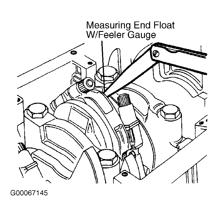
- Check end-float between connecting rods on each crankshaft journal. Clearance limits should be 0.15-0.37 mm (0.006-0.015"). See Fig 3.
- Tighten connecting rod nuts to 50 N.m (37 ft. lbs.). Fit oil strainer and joint washer.
 Courtesy of LAND ROVER NORTH AMERICA, INC.
 Courtesy of LAND ROVER NORTH AMERICA, INC.
 Courtesy of LAND ROVER NORTH AMERICA, INC.